200 in 1 Circuit Kit Causing Confusion

Thread Starter

bwilliams60

Joined Nov 18, 2012
1,442
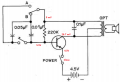
So I was playing around yesterday and decided I would pull out my old 200 in 1 Kit and build a circuit and see how things work, just for fun. Should have left well enough alone. Can someone explain current flow through this simple circuit. I am a conventional theory guy dealing with automotive all my life so if it can be done that way, even better. My second question is, why do I have a higher voltage on my base than my source? I am suspecting that the capacitors are causing this but then I am not sure why there would be flow through my transistor if my base is higher than my emitter? I have attached a diagram with my voltages on it. Thanks in advance for your help. Cheers!
 

Attachments

Thread Starter

bwilliams60

Joined Nov 18, 2012
1,442
The circuit is working exactly as it should. All voltages are measured with my negative probe on the negative terminal of my power supply. Here are the pictures of the transistor from a scope point of view. Even more confusing but maybe it is me. All taken on Autoselect.
Base, Collector, Emitter - referenced to ground.
 

Attachments

Last edited:

Thread Starter

bwilliams60

Joined Nov 18, 2012
1,442
No answers??? I am perplexed. I am pretty sure for most this is not a hard question so looking for a liitle help here. Just looking for a deeper understanding of circuitry and why it works the way it does.
 

Reloadron

Joined Jan 15, 2015
7,501
I am going to wing it. The schematic looks like a one transistor CPO (Code Practice Oscillator). The switch labeled A and B looks like it can select between two audio frequencies. I don't think you can reliably measure what you are seeing as DC voltages. This is where your scope is your best friend as you can actually see your oscillator oscillating. As to a detailed theory of operation? Sorry as it has been too long. Hopefully another member can help with that. I know we have members familiar with this type circuit.

Ron
 

Thread Starter

bwilliams60

Joined Nov 18, 2012
1,442
Thank you Reloadron for your analogy. It helps a bit. I am hoping to understand a bit more about how circuits react by building these simple circuits but there is no explanation in the book as to how it works. It just mentions what happens when capacitors get together in series and parallel. I would like to build this on LT Spice but not sure it can be done as I don't have much experience in that arena either. I guess it will just remain a mystery to me. Cheers.
 

DickCappels

Joined Aug 21, 2008
10,153
The base winding of the transformer will have the battery voltage plus the collector's waveform on it, allowing it to reach a higher voltage than on the battery. This is the same blocking oscillator as used in "Joule Thief" LED power supply circuits, but with added feature of a speaker.
 

Thread Starter

bwilliams60

Joined Nov 18, 2012
1,442
Thank you Dick for that explanation. It makes a little more sense now. and I just learned about blocking oscillator circuits so thank you for that as well.
 

KL7AJ

Joined Nov 4, 2008
2,229
No answers??? I am perplexed. I am pretty sure for most this is not a hard question so looking for a liitle help here. Just looking for a deeper understanding of circuitry and why it works the way it does.
The ELECTRONS always flow against the arrows. It's all Ben Franklin's fault.
 
Top