Facebook
 Google
 GitHub
 Linkedin
Hi all, thanks in advance for the time spent on helping me out on this project. I greatly appreciate! ")
Goal
To build a dual-channel, 2-way speaker switch to control the output from the hifi amplifier to 4 speakers, speaker set 1 and 2, that are located in two different rooms.
The idea is to be able to activate speakers set 1, 2 or 1+2.
The numbers
- Amplifier output: 70W + 70W (4 ohms at 1 kHz) DIN Power output. (As stated on the service manual)
I know this is fuzzy figure. The amp is an old Sony TA FE-370. For the sake of start designing, I have assumed this figure to be the constant output power from the amp, leaving headroom for possible spikes in power. As soon as I will receive a new multimeter, I will attempt a more detailed measurement of the output, choosing the final components accordingly.
- From those numbers, using Ohm's law, I derived volts and amperes:
P = 70 watts
R = 4 ohms
Output voltage = √P * R = √70 * 4 = 16.7 volts
Output current = √P / R = √70 / 4 = 4.18 amperes
- Total resistance of the parallel circuit:
Number of resistors = 2
Resistance = 8 ohms
Total resistance = resistance / number of resistors = 8 / 2 = 4 ohms
Design

Approach
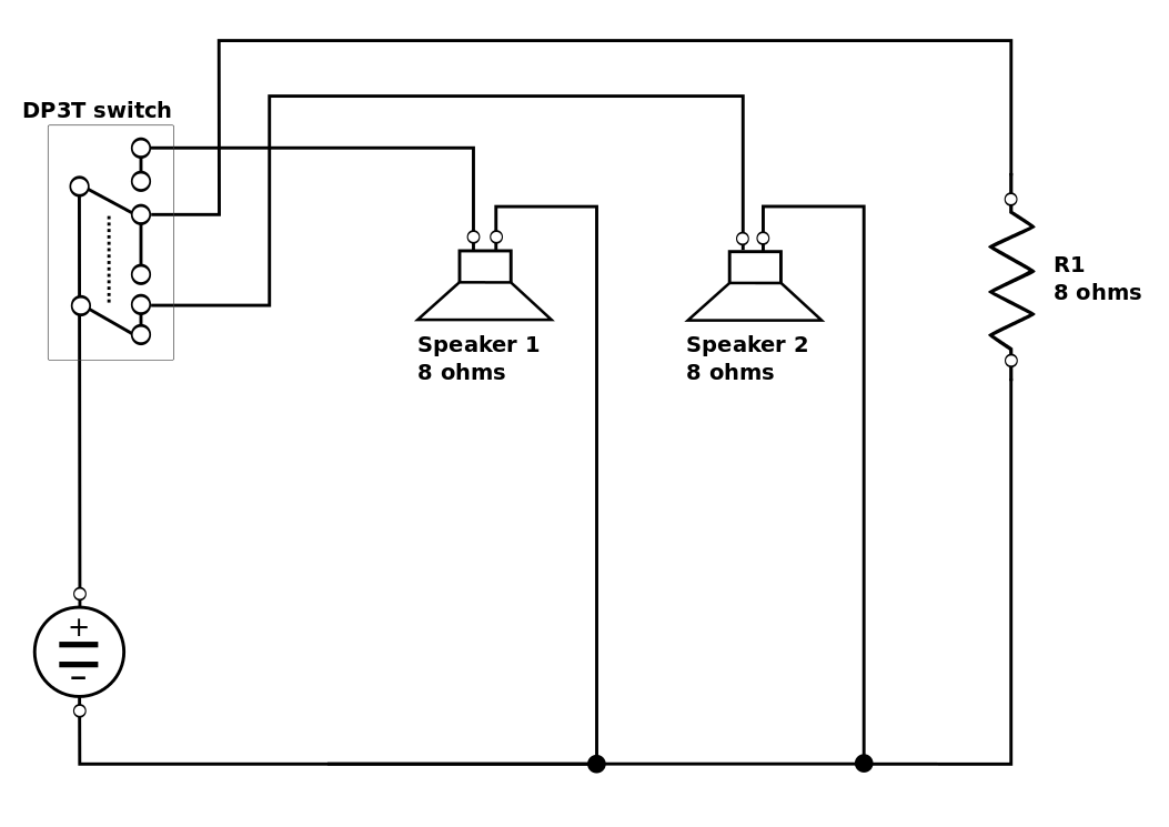
The schematics above shows the design for a mono-channel switcher, which will be duplicated for the actual use (example is wired to Left channel).
Following the idea on this Wikipedia page, https://en.wikipedia.org/wiki/3-way_lamp, the DP3T switch controls the positions necessary to activate each set of speakers at one time, or both at the same time (1, 2 or 1+2).
A dummy load replaces one of the speakers when just the set of speakers 1 or 2 is working. This is in order to maintain the overall resistance constant.
Technical data for components
DP3T switch:
Contact Voltage AC Nom: 250V; Contact Voltage DC Nom: 28V; Contact Current Max: 5A;
Dummy load
Resistance: 8ohm; Power Rating: 50W; Resistance Tolerance: ± 1%;
Questions
1. I'd appreciate a general feedback on the design. Is it well designed? Is it gonna work? Any drawbacks you can think of, or possible improvements?
2. Given the numbers for current and voltage, would the circuit be safe to use as it is, once wired?
Thanks a lot, please feel free to ask for more details and/or slap the total newbie!
Michele
Goal
To build a dual-channel, 2-way speaker switch to control the output from the hifi amplifier to 4 speakers, speaker set 1 and 2, that are located in two different rooms.
The idea is to be able to activate speakers set 1, 2 or 1+2.
The numbers
- Amplifier output: 70W + 70W (4 ohms at 1 kHz) DIN Power output. (As stated on the service manual)
I know this is fuzzy figure. The amp is an old Sony TA FE-370. For the sake of start designing, I have assumed this figure to be the constant output power from the amp, leaving headroom for possible spikes in power. As soon as I will receive a new multimeter, I will attempt a more detailed measurement of the output, choosing the final components accordingly.
- From those numbers, using Ohm's law, I derived volts and amperes:
P = 70 watts
R = 4 ohms
Output voltage = √P * R = √70 * 4 = 16.7 volts
Output current = √P / R = √70 / 4 = 4.18 amperes
- Total resistance of the parallel circuit:
Number of resistors = 2
Resistance = 8 ohms
Total resistance = resistance / number of resistors = 8 / 2 = 4 ohms
Design
Approach
The schematics above shows the design for a mono-channel switcher, which will be duplicated for the actual use (example is wired to Left channel).
Following the idea on this Wikipedia page, https://en.wikipedia.org/wiki/3-way_lamp, the DP3T switch controls the positions necessary to activate each set of speakers at one time, or both at the same time (1, 2 or 1+2).
A dummy load replaces one of the speakers when just the set of speakers 1 or 2 is working. This is in order to maintain the overall resistance constant.
Technical data for components
DP3T switch:
Contact Voltage AC Nom: 250V; Contact Voltage DC Nom: 28V; Contact Current Max: 5A;
Dummy load
Resistance: 8ohm; Power Rating: 50W; Resistance Tolerance: ± 1%;
Questions
1. I'd appreciate a general feedback on the design. Is it well designed? Is it gonna work? Any drawbacks you can think of, or possible improvements?
2. Given the numbers for current and voltage, would the circuit be safe to use as it is, once wired?
Thanks a lot, please feel free to ask for more details and/or slap the total newbie!
Michele