(2) 120v input circuits , single 120v output relay

Thread Starter

abestgen

Joined Aug 27, 2020
7
Hello,

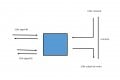
I have two 120v signals from two control panels that I need to condense down to a single 120v feed to run a motor. I don't believe the commons are shared. I have a constant 120v feed I can use as a source as well if I want to use the 120v signals just as closure signals. As either panel may send a signal at any time I want the two sources to stay separate at all times. can someone help me figure out what I need for relay(s) and a diagram?

thanks in advance
 

MaxHeadRoom

Joined Jul 18, 2013
28,681
I assume you want an OR condition?
You could use two small signal relays and a N.O. contact on either pick up the motor contactor/relay.
Also remember the NFPA79 colour coding if the separate control circuits end up in a separately powered enclosure. (Orange conductor colour).

Max.
 

MaxHeadRoom

Joined Jul 18, 2013
28,681
What is the motor power?
Do you need a contactor and O/L (overload)?
When done profesionally, generally a couple of ice cube relays such as Omron MY4Z Idec RJ22S-C-A120 etc.
Is this for personal use or an industrial installation?
I can draw it out, have you done control wiring before?
Max.
 
Last edited:

Thread Starter

abestgen

Joined Aug 27, 2020
7
the motor is operated by a separate panel that accepts a 120v input (from this set up). so all the components for it are covered, I just need to give it a single input signal so it can close it's 208v relay.
it's an industrial application and just something I can't get my head around.
I would greatly appreciate you drawing it out. I have done some control wiring before, mostly parts swapping and rewiring existing panels based on directions from a factory engineer.
thank you!
 

Thread Starter

abestgen

Joined Aug 27, 2020
7
i have to supply 120v to a landing point on the motor control panel, this is used by the panel as a contact closure on the 208v relay.
 

Reloadron

Joined Jan 15, 2015
7,515
If all you want is to use a 120 VAC signal as a control, as in low current less than 1 amp for example and they do not share a single common then a double pole three position switch would work as a manual means of selecting the 120 VAC control of your choice.

Ron
 

MaxHeadRoom

Joined Jul 18, 2013
28,681
Do you mean you have to supply a 120v supply source to the panel in order to pick up the panel motor relay?
If so, you show two sources to provide a common switch source, can either source be used?
Or do you just have to provide a contact closure?
It does not really seem clear?
Max.
 

MaxHeadRoom

Joined Jul 18, 2013
28,681
If all you want is to use a 120 VAC signal as a control, as in low current less than 1 amp for example and they do not share a single common then a double pole three position switch would work as a manual means of selecting the 120 VAC control of your choice.

Ron
That would be manual. As I understand it from the OP, the need is for automatic selection of
 

Thread Starter

abestgen

Joined Aug 27, 2020
7
yeah I can see how this isn't the clearest description.
so the motor panel uses 208v for all motor functions and a 120v input signal as a call signal to start the motor. the 120v serves no other function that I am aware of. historically we have a 120v signal that comes from a set of relays (signal #1) that get a low level signal from float switches. This has worked flawlessly for 7 years.

Now I need to add a new start signal to the mix to tell the motor to turn on (signal #2) this is coming from a panel that previously had a separate motor control that is no longer needed.

As I cannot add another relay to the panel at source #1 due to the fact it's at the wrong end of the building and has no space, my plan is to use these two 120v signals to close a set of relays to send a 120v signal to the motor panel. I have to do it in a way that an input from either source closes the relay and sends the signal, and if both signals are hot I don't cause a problem.

so I can use either source independently to call for the motor if I set a relay up as a switch, or i can use either source to close contacts to flow from a constant power to the motor panel.
 

Thread Starter

abestgen

Joined Aug 27, 2020
7
I assumed the same as @sghioto
IDEC RJ1S-C-A120
Max, thanks for this and thanks to everyone for your input! would you mind dumming it down a step for me?

in your diagram i just need to run a set of jumps from each source power landing and each power output so that either signal will close the circuit regardless of which input is energized and in the case of both being energized there will be no harm as it's just the same source power on a loop. right?
 

Tonyr1084

Joined Sep 24, 2015
7,894
120VAC on either relay (or both) will result in switching the motor on. 208VAC goes to your motor.
This is basically the same thing as in post #11. @sghioto already pointed out. Just used your drawing.
1598566705931.png
 
Top