1HZ Clock From A 10Mhz Oscillator Module

Bordodynov

Joined May 20, 2015
3,426
Thanks Bordodynov.

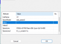
It would be really helpful if I had someone's actual .asc file. A picture does not help. I suspect that
the problem I am having is with the path and/or the parameters in the CD4060B Component
Attribute Editor.


M
You have entered incorrect parameters for low-frequency quartz. Three orders of magnitude less and an order of magnitude more.
If you use my library, then do not place file access on the diagram. I tried to calculate the circuit in LTspice, but the calculation is slow. So I created a hierarchical model of the CD4060 in Qpice and did the calculations. This took a minute and a half of computer time.
 

Thread Starter

maker_2023

Joined Nov 20, 2023
199
You have entered incorrect parameters for low-frequency quartz. Three orders of magnitude less and an order of magnitude more.
If you use my library, then do not place file access on the diagram. I tried to calculate the circuit in LTspice, but the calculation is slow. So I created a hierarchical model of the CD4060 in Qpice and did the calculations. This took a minute and a half of computer time.
I used your model and used the parameters specified in your .asc file. If my parameters are incorrect
then why not share?
 
Last edited:

Thread Starter

maker_2023

Joined Nov 20, 2023
199
It works very well:
1706379503198.png
I have a circuit that Bordodynov sent me in post #45. I made no changes to it and it does not work. Yours
does show an output but his just shows a straight line at 0 volts. Are you using Model QZS32768?
There must be something different somehow. Would you mind posting the .asc and I can run it at my end.
Thanks,
M
 
Last edited:

Danko

Joined Nov 22, 2017
2,172
I have a circuit that Bordodynov sent me in post #45. I made no changes to it and it does not work. Yours
does show an output but his just shows a straight line at 0 volts. There must be something different some
how. Would you mind posting the .asc and I try run that at my end.
Thanks,
M
I used same @Bordodynov's file from post #45, without changes.
After simulation is running, see on status bar.
When "Simulation Time" will 2 sec
and "Transient Analysis" will 100% done,
then your simulation is fully finished.

1706385426118.png
 

Thread Starter

maker_2023

Joined Nov 20, 2023
199
I used same @Bordodynov's file from post #45, without changes.
After simulation is running, see on status bar.
When "Simulation Time" will 2 sec
and "Transient Analysis" will 100% done,
then your simulation is fully finished.

View attachment 313740
Hi Danko:
I am just curious, how long should the simulation take? Perhaps I don't wait long enough.
It has been runing for 10 or 15 minutes and the status bar is not changing. I have also
attached my settings in the Component Attributes Editor.
M.
 

Attachments

Last edited:

Danko

Joined Nov 22, 2017
2,172
Bordodynov's circuit still does not work. The sim goes so far and then freezes.
Obviously, there is something different between our circuits and I guess it
is a big secret.
Why would I want this?
M.
I think it may be difference between computers.
@Bordodynov's file on Intel(R) Core(TM) i9-10900, 10-core CPU @ 4.49 GHz, 16 GB,
Windows 11, LTspice XVII,
time of simulation = about 3 hours, on speed 200 μs/s, without problems.
Your image in post #53 indicates that your sim didn't run to completion and it
might have froze at Simulation Time = 26.7749 ms or 30.6894 ms like mine did.
My simulation was not frozen, I took image from running program.
 
Last edited:

Bordodynov

Joined May 20, 2015
3,426
I used the Qspice program and the simulation time on my home laptop was:
Total elapsed time: 419.938 seconds
On my work computer the simulation time is 90 seconds.
I have posted below the general electronic circuit and the contents of the hierarchical circuit.
cd4060+32kHz.png
 

Attachments

Top