
 Facebook
 Google
 GitHub
 Linkedin
Hi all,
Got to the point where I could use a bit of help!! I'm trying to repair a transmission control PCB from a 1990's tractor.
It's got a old school 87c196 KC on it with a couple memory chips, latches and loads of other stuff.
Last night after checking ALL the sensors switches and inputs (2 pages of tests I'd written out) all pointed to the PCB. I had the cover off and started scoping the processor, and just briefly everything worked, then stopped again!
I've got it on my bench now, have checked data lines traces, resoldered the processor.
With a bit more examination found the following.
Clk out is working
Ale/adv are quiet
Rd is quiet.
It's a while since I've messed with stuff like this.
Am I right in thinking rd should be clocking program data in from the memory?
I'd checked rd resistance to gnd but just now have read it's active low so will check to vcc incase it's something on the rd line holding it high?
Other than that I suppose it must be the processor playing up? Just seems strange poking a pin with the scope made it work but I haven't recreated that?
In normal operation should rd be pretty active?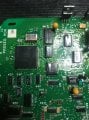
Cheers Geoff
Got to the point where I could use a bit of help!! I'm trying to repair a transmission control PCB from a 1990's tractor.
It's got a old school 87c196 KC on it with a couple memory chips, latches and loads of other stuff.
Last night after checking ALL the sensors switches and inputs (2 pages of tests I'd written out) all pointed to the PCB. I had the cover off and started scoping the processor, and just briefly everything worked, then stopped again!
I've got it on my bench now, have checked data lines traces, resoldered the processor.
With a bit more examination found the following.
Clk out is working
Ale/adv are quiet
Rd is quiet.
It's a while since I've messed with stuff like this.
Am I right in thinking rd should be clocking program data in from the memory?
I'd checked rd resistance to gnd but just now have read it's active low so will check to vcc incase it's something on the rd line holding it high?
Other than that I suppose it must be the processor playing up? Just seems strange poking a pin with the scope made it work but I haven't recreated that?
In normal operation should rd be pretty active?
Cheers Geoff




