 Facebook
 Google
 GitHub
 Linkedin
Hello everyone!!
As the title suggests, this will probably be a piece of cakes for most of you guys on here!
But me as a newby to electronics and circuits have a much more difficult time to be sure of my schematic.
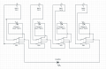
I want to make a battery pack made out of 4 18650 battery hooked up in series.
Another requirement is being able to charge the batteries whilst in series. Now I am aware of the existence of circuits that charge series of batteries as well as levelling them but I want to be able to charge my battery pack with 5v (Planning on making a beefy 5v usb charger).
So here is my idea:
If I'm able to use 1 DPDT switch per battery to disconnect them from the serie and connected them to a TP4056 charger.
I think I got the schematics figured out -albeit it looking more like kids painting with the different colours, I'm not sure of my case and want to double check with someone who has extended knowledge of these things.
I'm all up for trail and error and believe it's (one of) the best way to learn. But since we're dealing with 18650 and I don't want to put everyone in my direct radius in danger as well as potentially cause a fire in my room, I want to be sure this thing is save.
Thank you if you made it this far and spending some of your time on my humble little problem, truly appreciate it!")
Ps. I did search this forum for similar threads and although "doby" over at this thread comes very close to what I want, there were unfortunately no answers given that could help me.
Pps. please don't skin me alive for my schematic drawing and/or skills in CircuitLab
As the title suggests, this will probably be a piece of cakes for most of you guys on here!
But me as a newby to electronics and circuits have a much more difficult time to be sure of my schematic.
I want to make a battery pack made out of 4 18650 battery hooked up in series.
Another requirement is being able to charge the batteries whilst in series. Now I am aware of the existence of circuits that charge series of batteries as well as levelling them but I want to be able to charge my battery pack with 5v (Planning on making a beefy 5v usb charger).
So here is my idea:
If I'm able to use 1 DPDT switch per battery to disconnect them from the serie and connected them to a TP4056 charger.
I think I got the schematics figured out -albeit it looking more like kids painting with the different colours, I'm not sure of my case and want to double check with someone who has extended knowledge of these things.
I'm all up for trail and error and believe it's (one of) the best way to learn. But since we're dealing with 18650 and I don't want to put everyone in my direct radius in danger as well as potentially cause a fire in my room, I want to be sure this thing is save.
Thank you if you made it this far and spending some of your time on my humble little problem, truly appreciate it!
Ps. I did search this forum for similar threads and although "doby" over at this thread comes very close to what I want, there were unfortunately no answers given that could help me.
Pps. please don't skin me alive for my schematic drawing and/or skills in CircuitLab
Attachments
-
 33.9 KB Views: 24
 -
 33.9 KB Views: 19
 -
 33.9 KB Views: 18
 -
 135.8 KB Views: 20
 -
 135.8 KB Views: 15


