12v battery charger from 50v

Thread Starter

fouad belkhadem

Joined Jun 28, 2018
26
Dears,

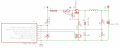
Need your help,i have two power modules 52v 30A each,i want to build 12v battery charger (13.2v) using this 2 modules and mosfet transistor.

Please any schematic or suggestion is welcome.

Thanks
 

crutschow

Joined Mar 14, 2008
38,535
Why do you want to use both modules?
One will give you more than enough current to charge a vehicle battery.

What charging current do you want?
For any current over an amp you will likely want to use a switching regulator to minimize power dissipation.
 
Last edited:

Thread Starter

fouad belkhadem

Joined Jun 28, 2018
26
Why do you want to use both modules?
One will give you more than enough current to charge a vehicle battery.

What charging current do you want?
For any current over an amp you will likely want to use a switching regulator to minimize power dissipation.
My espectationis use 2 just in case where i need boost,starting car direcly with this power supply.

Requested amps ,the max is better lets say 40A.
 

BR-549

Joined Sep 22, 2013
4,931
So you want a battery charger, and be able to start a car. Have you got the power module's data sheet and schematic?

Let's see what we're talking about.
 

BR-549

Joined Sep 22, 2013
4,931
All I get with that link is a page wanting me to install some kind of application.

Are you trying to sell something?
 

BR-549

Joined Sep 22, 2013
4,931
Ok, thanks. Interesting unit. I am by no means a power expert. Those units do have some kind of power sharing capability. Perhaps the installation docs explain the configuration. Or it might be automatic.

The problem is your voltage. I'm sure an engineer can design a DC-DC converter for it.

It is not simple.

But I would not go to the trouble. If this is just for personal use.....they have fairly in-expensive charger starter combos now. Light weight and portable. Not sure how they perform....never used one and I am skeptical.

If this for for hobby garage maintenance, I would consider a used commercial unit.

If you want to home brew with power supplies of that nature......14 volt high current switchers are in-expensive.

Perhaps a trade. Maybe sell and then buy. You don't use 48 to 53 volts DC do you?
 

Thread Starter

fouad belkhadem

Joined Jun 28, 2018
26
Thanks for suggestion,but i like to build thinks,also the quality is important since i have seen this modulea work for years without stop ,the quality is top.

May be firt thinks is to open the psu i iry to analyse and see if the voltge could be adjusted with some mods.
 

Thread Starter

fouad belkhadem

Joined Jun 28, 2018
26
Hi,

After a lot of tries with pc psu,and some mods,conclution is that is not good solution using pc atx power supply.

Still thinks that using the 50v 50a psu is best solution if add a buck converter that can produce at least 30A.

I found a circuit drived by microcontroller that i beleave is a good solution.

Attached the schematic,please need help with power stage.

It is possible to put 2 mosfets in parallel to increase output current (original design is 12A max).

Thanks
 

Attachments

crutschow

Joined Mar 14, 2008
38,535
I found a circuit drived by microcontroller that i beleave is a good solution.
That circuit is a bad design and looks like no-one ever actually built it, unless it was meant for a low current output.
Resistors R3 and R4 are way too high in value which will cause slow turn-on and turn-off of Q4, leading to its high power dissipation, possible overheating, and poor conversion efficiency.
Q4 needs a high current push-pull or totem-pole gate driver to rapidly charge/discharge it's high gate capacitance.

Yes, you can parallel two MOSFETs, but it's better to use one larger MOSFET if you can.
 
Top