Facebook
 Google
 GitHub
 Linkedin
Is the part something like this?:

It looks really small. I doubt it has more than two zeners back-to-back inside. It's also all-metal, which probably is to keep heat flowing to the outside.
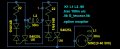
The TRIAC circuit will probably short the voltage from the alternator to it's sustaining voltage for the remaining of the semi-cycle once it's value reaches the triggering value, so the RMS value could get quite low.
It seems to me than there's no easier, cheaper, and effective way than using the two zeners.
The LM317 can be used to regulate AC, but it can go only to 40v maximum.
Or you could bridge-rectify it, and make a discrete voltage regulator with a resistor, zener, and emitter-follower transistor. If the alternator cannot supply much more current than the lamp needs to use, that means it's voltage will go down quickly when shunted, and maybe the linear rectifier won't need to dissipate tons of power. You will still need to put all this in a box used as heatsink and seal it, however.
It looks really small. I doubt it has more than two zeners back-to-back inside. It's also all-metal, which probably is to keep heat flowing to the outside.
The TRIAC circuit will probably short the voltage from the alternator to it's sustaining voltage for the remaining of the semi-cycle once it's value reaches the triggering value, so the RMS value could get quite low.
It seems to me than there's no easier, cheaper, and effective way than using the two zeners.
The LM317 can be used to regulate AC, but it can go only to 40v maximum.
Or you could bridge-rectify it, and make a discrete voltage regulator with a resistor, zener, and emitter-follower transistor. If the alternator cannot supply much more current than the lamp needs to use, that means it's voltage will go down quickly when shunted, and maybe the linear rectifier won't need to dissipate tons of power. You will still need to put all this in a box used as heatsink and seal it, however.