 Facebook
 Google
 GitHub
 Linkedin
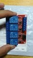
I bought a 12v 4channel relay module from AliExpress. I connected a 12v power supply to the postive and negative leads. Now when I touch a 12v +ve wire to any of the 4 input signals, the relay doesn't work. When I connect the two coil leads on the back of PCB the relay works perfectly. I need guidnace on how to make it work from the actual input signal leads.
What I am doing is that I have several 12v bulbs that I want to connect to an arduino nano. I want the bulbs to operate and send a signal to the relay which will close the switch and a 5v connection will form at the relay which will be connected to arduino.
What I am doing is that I have several 12v bulbs that I want to connect to an arduino nano. I want the bulbs to operate and send a signal to the relay which will close the switch and a 5v connection will form at the relay which will be connected to arduino.
Attachments
-
 361.5 KB Views: 21


