12F683 too few outputs

t06afre

Joined May 11, 2009
5,934
Does that mean that I could tie the anode of the LED to Vcc (with a resistor) and turn the LED on and off with software? If so, that solves my problem.
To be sure about this. One must confer whit your PIC datasheet. But yes I think so. And your description regarding this is also correct
 

Thread Starter

tracecom

Joined Apr 16, 2010
3,944
To be sure about this. One must confer whit your PIC datasheet. But yes I think so. And your description regarding this is also correct
From my reading of the datasheet (page 31,) I don't think so. It seems to say that the status of GP3 always is 0. But, I am not very good at understanding datasheets, so I may be wrong.
 

t06afre

Joined May 11, 2009
5,934
From my reading of the datasheet (page 31,) I don't think so. It seems to say that the status of GP3 always is 0. But, I am not very good at understanding datasheets, so I may be wrong.
Oh sorry. I had my mind someplace else. I am working on case of research fraud. And I have the last day only used AAC as breakpoint. The pin in question is input only I think. So of course my suggestion is no valid at all:eek: Have you considered the fast/slow blink variant
 

Thread Starter

tracecom

Joined Apr 16, 2010
3,944
Oh sorry. I had my mind someplace else. I am working on case of research fraud. And I have the last day only used AAC as breakpoint. The pin in question is input only I think. So of course my suggestion is no valid at all:eek: Have you considered the fast/slow blink variant
Yes, that will work, and is my fallback position.
 

MMcLaren

Joined Feb 14, 2010
861
Please clarify something? It sounds like you're using a pot' (and ADC) for setting a temperature set point but you're not using a display in normal operation, is that correct? So is the pot used to set the temperature set point one time only when you have the LCD hooked up and not used during normal operation?

Mike...
 

Thread Starter

tracecom

Joined Apr 16, 2010
3,944
Please clarify something? It sounds like you're using a pot' (and ADC) for s.etting a temperature set point but you're not using a display in normal operation, is that correct? So is the pot used to set the temperature set point one time only when you have the LCD hooked up and not used during normal operation?

Mike...
Correct. The display is used only during calibration.
 

Markd77

Joined Sep 7, 2009
2,806
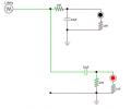
I've thought of something, not sure it's ideal. Use a high pass and a low pass filter and change the frequency output of the pin to light one or the other LED, you may have to do some calculations to get sensible value capacitors:
You may be able to get rid of some of the resistors.


Attachments

MMcLaren

Joined Feb 14, 2010
861
ok. does it have to be a pot? how about a switch or jumper connected to GP3 instead? use short presses to increment or decrement the setpoint and a long press to change direction (inc or dec)? Or use long presses to go from mode to mode. That is, do a long press to go from "increment" mode to "decrement" mode and another long press to go from "decrement" mode to "save" mode, etc. Each mode carefully displayed on your LCD.

Another option is to use GP3 and one other pin for a serial interface. Connect it to your PC via a $3 usb-to-serial adapter and adjust your setpoint using a terminal program. That leaves four I/O pins for your LCD, MOSFET, and LEDs.

BTW, I have some bi-color Red/Green LEDs in a two pin package so two I/O pins can be used to display red, green, yellow, and off states.

Regards, Mike...
 
Last edited:
Top