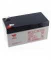
12 volt acid lead battery, which amp fuse?

#12

Joined Nov 30, 2010
18,224
Depends on the oscillator. The fuse is supposed to keep the wires from melting if the oscillator goes bad, not so much to protect the battery.
 

Thread Starter

Tony Elliott

Joined May 8, 2015
158
The battery only powers one oscillator, it is a 555 timer square wave based, when I measured the voltage where the frequency pot is I measured 6 volts. below is a schematic.
n41fl_datasheet.jpg
 

Lestraveled

Joined May 19, 2014
1,946
It is good that you posted the schematic. The oscillator itself draws less that .1 amp, but Q2, the output mosfet can drive many amps. Based on the spec of the IRF530 with no heat sink, I would fuse it at no greater than 5 amps. A 2 amp fuse would be very safe.

Edit: I looked this kit up. If you are going to just drive a small speaker, 2 amps will be more than enough.
 
Last edited:

Thread Starter

Tony Elliott

Joined May 8, 2015
158
It is good that you posted the schematic. The oscillator itself draws less that .1 amp, but Q2, the output mosfet can drive many amps. Based on the spec of the IRF530 with no heat sink, I would fuse it at no greater than 5 amps. A 2 amp fuse would be very safe.

Edit: I looked this kit up. If you are going to just drive a small speaker, 2 amps will be more than enough.
Thank you for your advice thats great! The oscillator will be plugged into a amplifier to power a speaker system.


AnalogKid

Joined Aug 1, 2013
11,042
In that case there might be some interface issues. The output of this circuit can sink current but not source any, a requirement for an audio source. A simple fix is to connect a 1 K resistor across X2-1 and X2-2 terminals to act as a pull up resistor. Second, the output is a 12 V square wave, huge in terms of a normal audio amplifier input range. Might not be a problem for your particular amp, but don't be surprised if your amp is running full blast with the volume control set very low.
One way to solve both issues is this:

1. Do not install Q2.
2. Install a 47 ohm to 100 ohm resistor from the Q2 Gate location to the Q2 Source location.
3. Install a jumper from the Q2 Gate location to the Q2 Drain location.
4. Reduce the size of the external fuse to something between 0.1 A and 1.0 A

An output that is much better suited to an audio amp input will be on X2-1. Important - do not connect X2-2 to anything. The return wire (shield) for the audio cable connects to the oscillator circuit Ground. This can be X1-2 or anywhere else in the circuit labeled GND.

ak
 

Thread Starter

Tony Elliott

Joined May 8, 2015
158
Thank you I'll try cutting out Q2 and seeing what happens.

In that case there might be some interface issues. The output of this circuit can sink current but not source any, a requirement for an audio source. A simple fix is to connect a 1 K resistor across X2-1 and X2-2 terminals to act as a pull up resistor. Second, the output is a 12 V square wave, huge in terms of a normal audio amplifier input range. Might not be a problem for your particular amp, but don't be surprised if your amp is running full blast with the volume control set very low.
One way to solve both issues is this:

1. Do not install Q2.
2. Install a 47 ohm to 100 ohm resistor from the Q2 Gate location to the Q2 Source location.
3. Install a jumper from the Q2 Gate location to the Q2 Drain location.
4. Reduce the size of the external fuse to something between 0.1 A and 1.0 A

An output that is much better suited to an audio amp input will be on X2-1. Important - do not connect X2-2 to anything. The return wire (shield) for the audio cable connects to the oscillator circuit Ground. This can be X1-2 or anywhere else in the circuit labeled GND.

ak
 
Top