100w LED Light need assistance with design

Thread Starter

sscsksl

Joined May 23, 2016
8
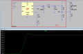
I am looking for technical advice on how to build a project. Please see attached presentation. Here are the questions. Thank you for your consideration.

1.Circuit breaker - correct item and size to limit current? Is a 120k ohm resistor more applicable?
2.Fuse, Is it needed? If so is 20A correct?
3.Switch – can it handle 20A?
4.Multimeter – If limited to 20 amps, is a shunt strap needed?
5.Wiring Diagram - Is this correct?
6.Resistor - Is it needed for a Pot? If so how many (2?) (as shown) and size (11k)?
7.Pot – is 10K ohm correct?
 

Attachments

Thread Starter

sscsksl

Joined May 23, 2016
8
Sorry, It dawned on me what you were asking for once I resent the PDF. I put together a list of all the components. The first two are the items request. Thank you for looking at this!

GEREE 250W Boost Converter DC/DC 8.5-48V to 12-50V Output Step-up Module Mobile Power Supply Max 10A

Specification:
- Module Properties: non-isolated step-up module (BOOST)
- Input voltage :8.5-48V
- Output voltage: 12-50V (adjustable)
- Output Current: 10A (MAX) (Please enhance heat dissipation if more than 6A)
- Output constant Current: 0.2 - 8A (please don't short the output to adjust the current)
- Easy to drive 65W 90W dual-core notebook.
- Conversion efficiency: 96%
- working frequency: 150KHZ
- Output Ripple: 2% (MAX) 20M-bandwidth
- Operating Temperature: Industrial (-40C to +85C) (ambient temperature exceeds 40C, lower power use, or to enhance heat dissipation)
- Dynamic response speed: 5% 200uS
- over circuit protection: yes
- Input Reverse Polarity Protection: yes
- Size: 70*46*13mm


LOHAS® 100W LED Chip Cool White Bulb High Power Energy Saving Lamp Chip

Drive Voltage:30-34V;Chip power:100w
Size (L*D):50mm*55mm Viewing Angle: 140 degree
Cool White.Color Tempreture:6000-6500K
Luminous(lv):8000-9000lm


Yeeco® Digital Multimeter Voltmeter Ammeter DC 6.5-100V 20A Voltage
Amperage Power Energy Meter

C. Test Range and Display format:
1.Power: test range: 0-2kW
Less than 1kW, display: 0.0-999.9W
1kW-2kW, display: 1000-2000W
2.Energy: test range: 0-9999kWh
Less than 10KWh, display: 0-9999Wh
More than 10kWh, display: 10-9999kWh
3.Voltage: test range: 6.50-100V(single-phase)
Display: 6.50-99.99V
4.Current: test range: 0-20A
Display: 0.00-20.00A

D. Specifications:
1. Working voltage: DC 6.5-100V
2. Test voltage: DC 6.5-100V
3. Rated power: 20A/2000W
4. Measurement accuracy: 1.0


TE Connectivity W54-XB1A4A10-30 Circuit Breaker; Therm; Push; Cur-Rtg 30A; Panel; 1 Pole; Vol-Rtg 250VAC

Brand Name

TE Connectivity / P&B

Part Number

W54-XB1A4A10-30

UNSPSC Code

39121633


ARCTIC Freezer A11 CPU Cooler for AMD, 150W Cooling Capacity, 3 Direct Touch Heatpipes, Vibration-Dampened Fan, 23dBA Noise

 150W Cooling Capacity Outperforms Stock Coolers, Supporting FM2/FM1/AM3+/AM3/AM2+/AM2

 3 Double-Sided Direct-Touch Heatpipes for Fast & Efficient Heat Dissipation

 92mm PWM Fluid Dynamic Bearing Fan on Vibration-Dampened Mount Operating at <23dBA

Resistors 11K OHM OHMS 1/4W 0.25W 1%

 Power (Watts) 0.25 (1/4 Watts)

 Resistant 11K OHM

 Tolerance +- 1%

 RoHS LEAD FREE


uxcell 10 Pcs 10K ohm 3 Pins 6mm Split Shaft Rotary Linear Taper Potentiometers w Knob

Product Name : Potentiometer;Resistance Value : 10K ohm;Adjustment Type : Top Adjustment

Type : Single Linear (Type B);Features : Knurled Shaft;Shaft Diameter : 6mm / 0.2"

Shaft Length : 8mm / 0.3";Mounting Thread Diameter : 7mm / 0.3";Base Size : 16 x 7.3mm / 0.6" x 0.3"(D*H)

Total Height : 24mm/0.9";Knob Size : 14 x 17mm/0.55" x 0.7"(D*L);Material : Metal, Plastic, Electronic Parts

Weight : 99g;Package : 10 x Potentiometer w Knob


ATC/ATO Water-resistant Fuse Holder - 10 AWG

Heavy duty, in-line fuseholder for ATC/ATO type fuses. 10 gauge wire for up to 30 amp rating.


GENSSI Auto Car Marine Boat Power Switch 4-pin (Stainless Steel Red LED Latching 18mm)

 Latching Type - Press On / Press Off

 Stainless Steel. IP65 waterproof. Up to 3A 250V AC Rated.

 4 Pin connections

 Requires resistor for the LED if using on 12V. Resistor included. Red LED. 3V LED.
 

DickCappels

Joined Aug 21, 2008
10,153
This might work, but the resistor may be a large problem. I cannot tell for sure from the information presented, but it appears that the power supply is intended to present a constant voltage to the LED, hence the need for a resistor. It would be far better to use a boost converter set up to supply a constant current. That way, you would not have to worry about getting a large enough resistor. The resistor problem is compounded by the fact that the LED voltage will drop, perhaps 10% as the LED warms up.

You're talking about 3 amps for the LED. If you were going to use a series resistor to limit current, then you would have to find a variable resistor that would safely handle the 3 amps. A 10k pot would not work (10x x 3A = 3kv).

I suggest you look for a LED driver that matches your needs.

By the way, most of that 100W will be dissipated as heat and LEDs need heatsinking not only to protect the LEDs but also to maintain efficiency at high power. Have you considered how you are going to get rid of all that heat?
 

Thread Starter

sscsksl

Joined May 23, 2016
8
I need to absorb everything you have written. As far as the heat, I have selected this heat sink with Fan. Please let me know if this will not wick the heat away

http://www.amazon.com/dp/B00HO9P0J6...lid=3GU2TTZF83SWA&coliid=I1NC2E8OH5P4LK&psc=1


ARCTIC Freezer A11 CPU Cooler for AMD, 150W Cooling Capacity, 3 Direct Touch Heatpipes, Vibration-Dampened Fan, 23dBA Noise

 150W Cooling Capacity Outperforms Stock Coolers, Supporting FM2/FM1/AM3+/AM3/AM2+/AM2

 3 Double-Sided Direct-Touch Heatpipes for Fast & Efficient Heat Dissipation

 92mm PWM Fluid Dynamic Bearing Fan on Vibration-Dampened Mount Operating at <23dBA

Resistors 11K OHM OHMS 1/4W 0.25W 1%

 Power (Watts) 0.25 (1/4 Watts)

 Resistant 11K OHM

 Tolerance +- 1%

 RoHS LEAD FREE
 

Thread Starter

sscsksl

Joined May 23, 2016
8
Would this be the correct Boost converter?
http://www.amazon.com/DROK-Converte...ir-20&linkId=2393373c8f0129791a207dcc4128cff5

DROK® 600W 12A DC Boost Voltage Converter 12-60V to 12-80V Step-up Power Supply Transformer Module Regulator Controller Constant Volt/Amp Car Regulated Laptop Battery Charger LED Driver Generator
Parameters:
Module Name: 150W boost module
Module properties: non-isolated module
Minimum voltage difference: 0V
Two Input voltage optional: select the input voltage by adjusting the jumper on the back of the PCB
Input/output Voltage 1: When Input DC 10-32V £¨aimed at application to wide input voltage)
Input/output Voltage 2: When Input DC 8-16V (aimed at application to 3 strings of lithium battery and 12V accumulator)
Output Voltage 1 : When Input DC 10-32V,Output 10-46V((adjustable, default 19V)
Output Voltage 2 : When Input DC 8-16V,Output 8-46V(adjustable, default 19V)
Input Current: 16A Max. (exceed 8A please enhance heat dissipation)
Output current: 8A Max. (exceed 4A please enhance heat dissipation)
Quiescent operating current: 15mA (12V to 20V, higher output voltage will increase the quiescent current)
Output power: 90W(natural cooling), 150W(enhance heat dissipation)
Capacitances:2x 470uF/35V(input) ; 2x 330uF/50V(output)
Operating temperature: -40¡ãc to +85¡ãc
Working frequency: 380KHz
Conversion efficiency: up to 95%
Operating indicator: Yes
Short circuit protection: None
Input reverse polarity protection: None (If need please install diode at input port)
Installation: 4x 3mm screws
Wiring: Terminals, Needn't solder, V-IN input, V-OUT output
Module size: 60mm x 50mm x 20mm

Testing:
16V to 19V, output current 3A, efficiency 94%
12V to 20V, output current 5A, efficiency 89.5%
12V to 30V, output current 3A, efficiency 89.2%
24V to 42V, output current 3A, efficiency 95.2%

Some Applications:
DIY a voltage Regulator, adjustable.
The power supply for electronic equipment.
Used as a car power supply, Power supply for laptop,PDA, or other digital products
DIY a notebook mobile power
 

DickCappels

Joined Aug 21, 2008
10,153
The heatsink looks promising as does the power supply. Very good!

Since this is not an established design expect to make some improvements as you go. From what I can see you have a good start.
 

Thread Starter

sscsksl

Joined May 23, 2016
8
I have been reading trying to understand more. I found this on Stack Exchange: Best practice is to control the current fed to a LED either by a series resistor (low power applications) or a switching current regulator (higher powers). This falls in line with your statement above on find a variable resistor that would safely handle the 3 amps.

Question, would a switching current regulator serve me well to "trim" the intensity of the LED? I assume I would be looking for one that can safely handle 3 amps?
 

dannyf

Joined Sep 13, 2015
2,197
Here is what I meant earlier.

What's within the red outline is a typical (adjustable) smps. It can be pretty much anything and the key here is that it attempts to adjust its voltage output so that it maintains a constant Vfb. That Vfb varies from module to module, based on the chips used. This particular chip I 'm using to demonstrate the principle has a Vfb of 2.2v.

Normally, you adjust R2/R3 to vary the output voltage.

To drive a led at a constant vurrent, all you need is a current sensing resistor R4, and your LEDs (D2/D3.....), and a connection from the middle of the two to Vfb -> within reason, R2/R3 values don't matter.

The current through the leds, as shown in the simulation, is determined by Vfb / R4. In this case, it is 2.2v/22ohm = 100ma. Regardless of the input voltage (at least > 2.2v + Vfwd(d2..d3)), the smps will maintain that constant current.
 

Attachments

dannyf

Joined Sep 13, 2015
2,197
So if you wish to drive your leds at 0.5amp, using one of those el-cheapo ebay LM2596 modules (Vfb=1.1v), R4 = 1.1v/0.5 = 2.2ohm.

the input voltage needed would be at least 1.1v + Vfwd for your leds.

This is probably the best value LED drivers out there. Beats out building your own.

Yes, I have done it myself many times.

And the basic principle can be applied to pretty much any smps, as long as it operates to maintain a constant Vfb. obviously, the lower Vfb and lower power dissipation over R4.
 
Top