There is your problem then,
10 MHz is viewed as a low frequency now days , when done on a PCB
Those no solder bread boards, are very high inductance / capacitance.
and if anything apart from new, the resistance of a contact is very very variable.
An oscillator is a very analog thing,
It has very high gain, and the phase shift is critical.
I'd imagine just putting your finger near the crystal up on those long wires will start / stop the oscillation.
If you want to make your own, put you oscillator on a bit of copper board,
mount the parts up side down, pins in the air, and keep wires SHORT.
with a decoupling capacitor on the board, and then send the clock to the solderless board.
You also seem to have a complete absence of decoupling capacitors,
you need 100 nf capacitors on each and every power pin to ground,
What's happening is all the noise from the buffers / counters on the PSU is being transmitted over all the wires, and being picked up by the oscillator wires.
I just ordered an oscillator module and some 0.1uF polyester caps for decoupling. Should be here in a week or so. I am just getting back into electronics after a very long absence so I am still having to stock some parts.
I just ordered an oscillator module and some 0.1uF polyester caps for decoupling. Should be here in a week or so. I am just getting back into electronics after a very long absence so I am still having to stock some parts.
Stacked film or wound film polyesters?
The wound film will have way too much ESL to be effective.
Use ceramic caps. Not only they are better at DECOUPLING than any film types, they will also be significantly cheaper.
To be fair to @dl324,
There "schematic" is evidently a LTspice simulation, which as you say does not include the power, I don't know how you would show the power in LTspice,
Where as the OP, had a hand drawn schematic, and we were asking about the circuit, trying to tease out how the oscillator was built, so in that case the decoupling was critical to the actual design.
OP, Please look at @dl324 circuit, and how small they have made the wires, how tight the circuit is.
Also look at how they have a capacitor to ground and a much higher resistor value,
See how hard it is, even when experts like @dl324 do it, it works , but only just ,
Bottom line, don't use solderless bread boards for analogue circuits.
He had a great way of building I MUST SAY PROTOTYPE
analog circuits on copper clad board, with the parts mounted up side down, Its all about knowing what you can get away with and cant,
which I m sorry only comes with experience.
I must have known this at one time, but forgot that BW specification for combo 1X/10X probes is for the 10X setting. When you operate at 1X, the probe conductor is a lossy wire and has a resistance of about several hundred ohms and the impedance of input capacitor on the scope can be relatively low (on the order of 1k at 10MHz).
That's what gives the "terrible" waveform I saw.
The signal with the 10X setting has a lot of ringing due to the inductance of the scope probe ground clip. I'll work on determining what dampening resistor to use to dampen the worst of the oscillations and post pictures with a 10X probe.
I also learned that for Tektronix probes, the specified probe bandwidth is for the overall "system" when used with an appropriate Tek scope. So I'll dig out a Tek probe. I usually use "cheap" probes, so a 10X 100MHz probe will be -3dB at 100MHz which is combined with any BW limitations of the scope. And much worse on 1X.
When I was an R&D tech at a well known company, almost all of my prototypes were done using that style. I soldered BNC connectors by points I wanted to probe and angled them so that I could use the shortest wire possible to connect to the net.
I also made use of the coil of wire that goes on the ground at the probe tip to cut down on inductance.
That reminds me of a 100MHz optical scope [probe] prototype I worked on. Wish I had one now...
There "schematic" is evidently a LTspice simulation, which as you say does not include the power, I don't know how you would show the power in LTspice,
And we don't know what technology the inverters are. I assume they'd be HC because that's what the OP was using, but that's just an assumption.
I don't think I've ever been able to run LTspice without a ground symbol in the schematic. But don't use LTspice much and I've never tried to do a simulation with digital logic...
Ground is the bottom of the graticule. Both sets of pictures are at 1V/div vertical sensitivity (Tek 10X probes change the displayed voltage on compatible scopes to be correct). Dampening with with a 150 ohm resistor using the standard 4-5" long ground lead. 7704A scope bandwidth is limited to 200MHz by the 7A26 vertical amplifier.
I have never built a crystal oscillator, only read about them. One thing I read was for best results have some way of limiting the drive so they are not stressed. Is it possible the oscillator is stressed? For 10MHz I bought several OSC5A2B02 second hand OCXO off ebay. With a stable voltage supply and a method of varying the control voltage they can be pulled to +- 1Hz reliably.
I have never built a crystal oscillator, only read about them. One thing I read was for best results have some way of limiting the drive so they are not stressed. Is it possible the oscillator is stressed? For 10MHz I bought several OSC5A2B02 second hand OCXO off ebay. With a stable voltage supply and a method of varying the control voltage they can be pulled to +- 1Hz reliably.
have a feed back circuit , which limits the amplitude
These TTL oscillators are fairly self limiting, provided you don't over load the output.
But as you did,
the cost of crystals and the components needed are normally more than a self contained oscillator as you have found,
Even in the commercial world,
its In my experience, its getting to where we dont use crystals, but oscillators.
Given that crystal oscillators are temperamental, there is a cost for each part placed on a board, and that the difference in cost between oscillators and crystals with bits is effectively zero, the cost of even one board in 1000 not working due to a crystal not working is more than any possible savings in crystal costs.
When I was an R&D tech at a well known company, almost all of my prototypes were done using that style. I soldered BNC connectors by points I wanted to probe and angled them so that I could use the shortest wire possible to connect to the net.
I also made use of the coil of wire that goes on the ground at the probe tip to cut down on inductance.
That reminds me of a 100MHz optical scope [probe] prototype I worked on. Wish I had one now...
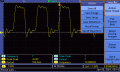
I got my 10 MHZ Saronix NCT050C oscillator module. It works okay. Attached is the output waveform
although it is not that square. The output voltage is 4.28 vpp. Running the output through a 74LS04
makes no difference.
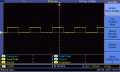
Here is the 10 HZ output from the divider chain. The output voltage is 3.60 vpp.
You have ringing caused by the fast edges and the parasitic inductance in your scope probe. The voltages you're reading won't be accurate until you dampen the oscillations. You can dampen by adding a small resistance in series with the probe. In my case, 150 ohms dampened the worst of the oscillations.
You have ringing caused by the fast edges and the parasitic inductance in your scope probe. The voltages you're reading won't be accurate until you dampen the oscillations. You can dampen by adding a small resistance in series with the probe. In my case, 150 ohms dampened the worst of the oscillations.
 Facebook
 Google
 GitHub
 Linkedin