10 band graphic equalizer

Thread Starter

Limzy

Joined Apr 26, 2019
22
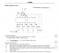
As a hobby I am dealing with electionics in my freetime and now I want to build a 10 band equalizer for a 3.5mm audio jack to equalize the output of my computer. I was looking around for a 5 band graphic eq IC which I wanted to use four time to get a 10 band stereo graphic eq and I found the LA3600 (If you now a diffrent IC please let me know). I looked in the datasheet and found a circuit diagram (page 4) which was just what I looked for, before I had this idea I delt with passive filters and as far I know analog grahpic equalizer just uses those to filter the frequency out that is needed but in this circuit diagram I was just looking for such a filter, but what I seen weren't any filters I now and I coudln't find anything to this circuit in the net. So now I am asking you how this is IC is doing it.

To determine the resonance frequency you need the formular sss.PNG but wouldn't this interrupt the High/ Low pass filters? Because you need a certain Capacity to filter out a certain frequency but do you just match the Capacity un the formular just by try and fail? And when it just gets the frequency you need you found out the cap value?

sorry if a question is dumb, I just working on understanding this since 3 days and I just fail, maybe someone can explain me how to use the IC right.
 

Attachments

BobaMosfet

Joined Jul 1, 2009
2,110
In examining the full datasheet, and looking at the application schematic (not the test schematic), they filter for all 5 channels simultaneously (using RC filters), and even give you 5 frequencies to set your RC filters to. To be honest, it's about as straightforward as you can get- I think you're simply over-thinking it, and haven't accurately represented the schematic in your attempt (which is why it isn't working), or the frequency output from your computer is not in the ranges you're expecting (or that it's filters are set for).

Expectation is a BIG part of electronics. Makes sure your expectation is accurate for what you've built. If you expect results other than what you've built will generate, you'll forever be lost in electronics. Just sayin'.
 

crutschow

Joined Mar 14, 2008
34,280
I was just looking for such a filter, but what I seen weren't any filters
It's an active filter with feedback, so it won't look like a standard RC passive filter.
To determine the resonance frequency you need the formular but wouldn't this interrupt the High/ Low pass filters? Because you need a certain Capacity to filter out a certain frequency but do you just match the Capacity un the formular just by try and fail? And when it just gets the frequency you need you found out the cap value?
Not sure I understand your confusion or what you mean by "interrupt the High/ Low pass filters". :confused:
The signal does not go through all the capacitors in series, They are just part of the overall feedback network for the internal op amp.
Each band has it's own value for C1 and C2 (C1 and C2 refer to the 2 different capacitors for each band, all different, 10 capacitors total).
Just follow the circuit diagram and the formula shown on page 4 for the desired filter frequencies, and you should be fine.
If you do the calculations for each band, I believe it will correspond to the values shown in the schematic for the band frequencies shown.

Using two in series for 10 bands would mean setting fo to different frequencies, of course.
I have a 10 band equalizer and it starts with 31.25Hz and doubles that for each higher band (i.e. 31.25, 62.5, 125, 250, ...).

upload_2019-4-26_16-10-27.png

Edit: There is an error in the part's description.
C3 is the input capacitor not C2.
 
Last edited:

Thread Starter

Limzy

Joined Apr 26, 2019
22
So if I would use a 0.0039uF capacitor and a 6.8uF instead of the original ones it would still filter the 108Hz? The nummers just have to be working with the formular. So using the Low/High pass formular to calulate the caps isn't right.

Thanks for all the answers I think it helpt me a lot.
 

BobaMosfet

Joined Jul 1, 2009
2,110
@Limzy-
You need to go on youtube and do some video watching on how RC filters work- if you understand what a filter is actually doing at the signal level, then this datasheet and the equations will become clear.
 

Thread Starter

Limzy

Joined Apr 26, 2019
22
My problem is I don't understand the relation between the resonance frequency formula and the formula to calculate the cut off frequency.

Is there a way, not by just trying out, to calculate the caps C1 and C2 in the schematic?

I don't think a "youtube video" can help me out there.
Because I will have 10 bands, I want other frequencys then those that are in the schematic.
 

crutschow

Joined Mar 14, 2008
34,280
So if I would use a 0.0039uF capacitor and a 6.8uF instead of the original ones it would still filter the 108Hz? The nummers just have to be working with the formular.
Yes, any values that satisfy the formula for the desired frequency will work.
But normally it's good practice to keep the two values relatively close together.
So using the Low/High pass formular to calulate the caps isn't right.
Yes, the equations for a single R and C filter do not work here.
Because I will have 10 bands, I want other frequencys then those that are in the schematic.
Then just calculate the capacitor values for the frequencies using the formula.
Do you have a problem with doing the math for that?
 

Thread Starter

Limzy

Joined Apr 26, 2019
22
No the math was not the problem, but when I looked at both formulas and put in the numbers it didn't make sense but thankfully you just made it clear.

I think my original question got answered
 
Top