0 To 6 Counting Circuit

Thread Starter

srtech90

Joined Feb 28, 2025
23
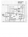
This circuit is supposed to count from 1 to 6. With a 7 segment display on the outputs it
shows 0 to 5 and then it resets. How would you make it display 1 to 5 and reset before it
displays a 6?
 

Attachments

Ian0

Joined Aug 7, 2020
13,097
You have it resetting as soon as it gets to 6, so it will display 6 but only for a VERY short time - as long as the reset signal take to propagate through the device, say about 100ns.
If you want to display 6 then you should reset it as soon as it gets to 7.
The lesson here is the difference between a synchronous reset and an asynchronous reset.
With an asynchronous reset (like the 4510) the reset happens immediately as soon as the reset pin goes to a logic high.
For a synchronous reset, the counter resets on the rising (or falling - depends on the counter) edge of the clock if the reset input is asserted.

just a hint - you can save one of those diode - replace one diode by the 10k resistor - and the logic still works.
 

AnalogKid

Joined Aug 1, 2013
12,043
Please re-draw the schematic to include reference designators for each component. It is very difficult to discuss connection changes without them

Configure the binary inputs for a 1 instead of a 0, and drive the LOAD input with the diode-diode-resistor node rather than the RESET input.

ak
 

Ian0

Joined Aug 7, 2020
13,097
SGS-Thomson's data sheet says
"
The
HCF4510B Presettable BCD Up/Down Counter
and the HCF4516B Presettable Binary Up/Down
Counter consist of four synchronously clocked
D-type flip-flops (with a gating structure to provide
T-type flip-flop capability) connected as counters.
These counters can be cleared by a high level on
the RESET line, and can be preset to any binary
number present on the jam inputs by a high level
on the PRESET ENABLE line. The HCF4510B
will count out of non-BCD counter states in a
maximum of two clock pulses in the up mode,
and a maximum of four clock pulses in the down
mode. If the CARRY-IN input is held low, the
counter advances up or down on each
positive-going clock transition."
and TI's says
Screenshot from 2025-03-08 16-37-39.png
No plagiarism at all!
 

AnalogKid

Joined Aug 1, 2013
12,043
No plagiarism at all!
Agree. That is common (and preferred) with licensed second sources.

Look at the original RCA datasheets for early CMOS CD4xxx parts, then check out Intersil, Harris, TI, etc. TI didn't bother to recreate the printed datasheets in Acrobat, they just scanned them into PDFs. They could do this because they are the sole owners of the original designs.

ak
 
Last edited:

Ian0

Joined Aug 7, 2020
13,097
It is, but since it produces a clock pulse at the same time, it will actually preset QA High.
It presets because it is asynchronous, not as I thought, not because there is a clock pulse at the same time, so it does count to 5.
It looks from TI's waveforms as though the preset occurs on the rising edge of the clock, but that is completely coincidental.Both Preset and Reset are asynchronous. It is not helped by TI referring to it as "Preset Enable" as it it needed some other event (e.g. a clock edge) for preset to occur.
The Philips datasheet makes this much clearer.
However, both Preset and Reset override clock, so a clock pulse happening whilst either reset of preset is asserted will be ignored.
 
Top