0 to 10 Binary Counter Help

Thread Starter

RamJam

Joined Apr 11, 2016
8
Hey all,

In college we have been given a example sheet to do in our own time, as its not coursework i didn't really take much notice of this, however sorting through my notes i realised i dont actually know how to answer one of the questions.

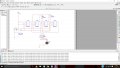
The task was to produce a binary counter from JK flip flops which counts from 0 to 10 (i.e. 0000 to 1010) then reset.

Ive produced a circuit that counts from 0 to 15 however i dont know how to make it reset back to 0 when it reaches 1011 or decimal 11.

I have uploaded a screen shot of my circuit along with this post, so my question is how to I make it reset back to 0 at 1011 or decimal 11?

Thanks in advance

RamJam
 

Attachments

WBahn

Joined Mar 31, 2012
30,045
What if you were only asked to modify the counter so that a single signal, called reset, would cause the counter to go to all zeros on the next rising clock edge?
 

Thread Starter

RamJam

Joined Apr 11, 2016
8
I understand that i can have a reset signal to reset the flip flops, however how do i make it do it only does this at 1011?
 

Thread Starter

RamJam

Joined Apr 11, 2016
8
What if you were only asked to modify the counter so that a single signal, called reset, would cause the counter to go to all zeros on the next rising clock edge?
I understand that i can have a reset signal to reset the flip flops, however how do i make it do it only does this at 1011?
 

WBahn

Joined Mar 31, 2012
30,045
I understand that i can have a reset signal to reset the flip flops, however how do i make it do it only does this at 1011?
One thing at a time.

Since this is a synchronous counter, you don't want to reset it when it hits 1011, you want to reset it on the next rising clock edge once it reaches 1010. But we can get to that later. For now, implement a synchronous reset as I described it. It's not enough to say that you understand that you can have a reset signal -- you need to DO it. Forget about that asynchronous clear input. Pretend it doesn't exist.
 

WBahn

Joined Mar 31, 2012
30,045
Clear for LS107 is asynchronous:
View attachment 104209
Which is why I suggest that he forget that it exists and design in a synchronous reset. It's extremely simple to do.

Using asynchronous clears for something like this is very hard to verify for proper operation. Consider that the outputs are synchronous so that they all change (nominally) at the same time. But, in reality, they will change at slightly different times. So your counter goes from state 0111 to state 1000. Every bit is changing and the order in which they change is indeterminate. That means that any possible state can appear as a glitch state and the reset logic can thus present a glitch to the asynchronous reset inputs. To make matters worse, that glitch might be long enough for some of the FF to respond to and not others. And all of that is dependent on supply voltage and temperature and the phase of the moon.
 

Thread Starter

RamJam

Joined Apr 11, 2016
8
Thanks for the help guys, but had a brain wave while at work, as im an aeronautical engineer by day. My solution was to use a a three input AND gate connected to Qa, Qb and Qd. when the counter reaches 11 this gives a logic HI result and is unique to only 11. From here i used a NOT gate which inverted the logic HI to LOW, this is connected to the reset line in the circuit, thus bringing the counted back to 0000 and starting over.

Cheers again for your help.
 

dl324

Joined Mar 30, 2015
16,911
My solution was to use a a three input AND gate connected to Qa, Qb and Qd. when the counter reaches 11 this gives a logic HI result and is unique to only 11. From here i used a NOT gate which inverted the logic HI to LOW, this is connected to the reset line in the circuit, thus bringing the counted back to 0000 and starting over.
Read @WBahn's comment about random resets when the count transitions from 7 to 8.
 
Top