See what parts you can get locally. Ordering single quantity resistors on-line will be expensive. You'll pay ten cents for a penny resistor and probably 10X more for shipping.
To save money, you can reuse the existing rectifier diodes. You might be able to use the 500uF filter cap but, as AK pointed out, they're old and possibly dried out. Without an oscilloscope to look at the filtered DC, it might cause some difficult to debug problems.
Go through your parts and make a list of what you need. I have LM317, resistors, diodes, LEDs, and caps and would be willing to send you whatever I can mail for a stamp or two. If you have something to trade; even better...
So I took all the parts, well mostly out of the case. I will reuse the diodes, potentiometer gang, meter and terminal strips. The rest rest is either considered bad or worthless(mostly just wires, the resistors if good will go to other stuff). As for the transformer, I tested it off my variac. Secondary winding puts out 73v. Center tap to either winding is 35ish volts. Would that be a problem? The rest of everything looks good. I'll try to hit a RadioShack soon and see what parts they may have before ordering online. Even if a little more it's better then a week from us or way more from China.
A 35 VRMS secondary will be a problem. I'm surprised they would use a 50V filter cap on it. To use an LM317, it needs to be no more than 40V input to output differential.
Do you have any better options than RadioShack? Their prices for most components are pretty high. Of course, if you have to drive any distance, gas will cost you more...
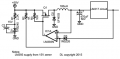
I gave this some thought and think a simple tracking, switching preregulator is probably the best way to go. This will also lower dissipation in the LM317 to a few watts max.
That will require a power P channel MOSFET, a couple zeners, a fast diode, a comparator (LM393), a few more resistors, and a capacitor.
I suspected this, which is why I asked about it in post #13.
One option is to use 1/2 of the transformer and a full wave bridge. Sometimes a transformer designed for a full wave center tap like yours cheats a little bit on the secondary wire gauge because only 1/2 of the secondary is making heat at any time. Given the physical size of the transformer I think it will be fine running 1/2 of the secondary all the time. Your max DC output would be limited to about 20 V, but the 317 would be happy. Not a perfect solution, but an option.
Another option is to take a play from the original regulator circuit. It has 2 transistors in series so neither one has the entire source voltage across it. The 2N307 is rated for 35 V max, yet two of them ran in a 49 V environment for years. With three components you can add a power clipper after the rectifiers and before the LM317, guaranteeing that it never sees anything outside of its ratings but always has enough headroom for the full 30 V output range. And your heatsink already has a space for a 2nd power device...
Well I just got back from RadioShack. It's too bad the one in Laramie closed as I have to go to Cheyenne for one. I knew I should have gotten more diodes. Well I got the parts I needed. They didn't have a 390ohm resistor so I got 330 and 33phm resistors. Or I can do a potentiometer. Also got a prototype board for my circuit board. I added a bnc plug to go with the banana jacks on the front. I have so many of them. They were a 20 pack for 6 from China. Have like 17 left. So as for the high voltage problem. What can be done about with lets just assume no extra parts beside some spare parts. I do have high wattage resistors. Do you think it would be fine to add a high wattage in series with the transformer primary? I'm thinking say a 39ohm in series would drop the secondary a bit. I may have a lower ohm.
What pins for the lm317 are which? The RadioShack print for that is too hard to make out. And is the heat sink connected to any pin? Is it fine to have the heat sink grounded? Thanks for the help
PS- Cheyenne is a 45 minutes drive from my house and Laramie 20-30 minutes.
So as for the high voltage problem. What can be done about with lets just assume no extra parts beside some spare parts. I do have high wattage resistors. Do you think it would be fine to add a high wattage in series with the transformer primary? I'm thinking say a 39ohm in series would drop the secondary a bit. I may have a lower ohm.
Using resistors to drop the voltage isn't practical. At low current, you wouldn't have enough drop. At high current, you'll have a lot of power dissipation in the resistors.
My idea for dropping the voltage with a preregulator requires additional components.
So I got a 12ohm 5w resistor. Going to try that and see what happens. On the primary of course
So a 680ohm 5watt and a 12ohm 5w in series get my secondary to 31.5vac. Now I'm rolling! The 680ohm was burning hot which led me to put the 12 and 680 in series. 10watts total. So with the lm317, since the output and heat sink are together what can I do? I don't have any heat sink insulating pad things. And I wanted this case to have a new 3 prong grounded case. Shall I just not ground it then?
So a 680ohm 5watt and a 12ohm 5w in series get my secondary to 31.5vac. Now I'm rolling! The 680ohm was burning hot which led me to put the 12 and 680 in series. 10watts total.
In the primary, those resistors are dissipating a total of 20W; they're undersized. If you're going to do that, and I don't recommend it, put them in the secondary where they'll dissipate a third of the power and still drop the voltage.
So with the lm317, since the output and heat sink are together what can I do? I don't have any heat sink insulating pad things.
If you use my preregulator idea to drop the voltage differential on the LM317 so it will dissipate 3W max, you could probably use a TO-220 heatsink and not have to worry about isolation.
And I wanted this case to have a new 3 prong grounded case. Shall I just not ground it then?
In the primary, those resistors are dissipating a total of 20W; they're undersized. If you're going to do that, and I don't recommend it, put them in the secondary where they'll dissipate a third of the power and still drop the voltage.
If you use my preregulator idea to drop the voltage differential on the LM317 so it will dissipate 3W max, you could probably use a TO-220 heatsink and not have to worry about isolation.
I recommend always grounding the case.
As for the dropping resistors that's weird. No matter the ohms law math I do it doesn't have the right numbers. The transformer draws 60ma. At a total resistance of 726ohms including dropping at 123v. Nothing is right! Going to check that out a little more in the morning with my watt meter. I made a little start on the circuit board. Got two potentiometers in place. One for the meter the other at 385ohm(the closest I could get). I had to use one of my 0.1uf 630v orange drops in this. And then a 68ohm plus a 15ohm in series to get as close as possible to 85ohms. Well I'll finish working tomorrow. I'll have to find a power cord for this. Still need to understand that lm317 and its heat sink so I don't blow something.
As for the dropping resistors that's weird. No matter the ohms law math I do it doesn't have the right numbers. The transformer draws 60ma. At a total resistance of 726ohms including dropping at 123v. Nothing is right!
So if I have a 12, 39, 78, 140, 680 and 10k all 5watt. What is the best to get 20-25 watts while still being around 700ish ohms? I don't want them in the secondary since that won't always be an even load I don't want it to drift upwards if I don't have anything connected. I may just use my variac at 88v until I get a resistor of correct value and test this current combo and see how that works out. I'll report that back soon.
So with all my power resistors together I can get a 54ohm 35w block. With the transformer after a diode and into a 300uf capacitor I get about 50vdc. How would the 54ohm block do if it was in the secondary? Would it work there. The only power resistor was that working on the primary was the 680ohm. That transformer just doesn't draw enough for the lower combos to work well.

 Facebook
 Google
 GitHub
 Linkedin



 . A self oscillating, switching, tracking preregulator...