0-30v and 0-6v power supply schematic?

Thread Starter

PrincessWoona

Joined Nov 30, 2015
53
I don't think the transformer will give enough current. I can try but I don't want to damage it. As for the lm317/350 I thought as i don't plan on drawing a large current the lm350 would fair better without me having to worry about my heat sink being perfect. I kinda plan on using the original metal piece that separated half the Eico case as the heat sink. Otherwise buying a large heat sink just for would be more money and more wasted space. As for using two pots I can see if maybe my one 2k is ok. I'm not sure as it sure has sparked a lot in there. That could maybe allow me to do a 2k resistor in parallel with one. I'm thinking that would then be 1k and adjusting the pot would give me between 0 and 1kohms. Correct me if I'm wrong. And I have plenty of dpdt and multipostion switches to use. Pulled them from a broken oscilloscope.
 

dl324

Joined Mar 30, 2015
18,403
IAs for the lm317/350 I thought as i don't plan on drawing a large current the lm350 would fair better without me having to worry about my heat sink being perfect.
The LM350 just has a bigger pass transistor. You still need to be concerned with power dissipation.

Inadequate heat sinking shouldn't damage the regulator, but it won't be regulating.
 

fkjhdsr7gik

Joined Oct 9, 2015
7
A radical solution.... use a dimming circuit for inductive loading, and vary the voltage across a transformer. I made one for a light source for a microscope stage. Worked perfectly except was noisy (acoustic), but that is standard for this method.
 

AnalogKid

Joined Aug 1, 2013
12,174
I don't think the transformer will give enough current.
i don't plan on drawing a large current ...
If the EICO transformer made enough current before, it will with a new regulator. Nothing being discussed will alter the basic operational parameters of the original supply. Same voltage range, same current capability, etc. The only significant change will be much better regulation, with overcurrrent and overheating protection built-in.

The original regulator split the pass transistor heat between two devices, which is hwy it didn't need a fan. Today's adjustable 3-terminal regulators can handle 5 A or more, but it is all in one device so it will run hotter than the original pass transistors under the same output conditions. As mentioned, there is a very common application circuit that adds an external power transistor to the 317 or 350 circuit to share the load and spread out the heat. My guess is that you will not need it, especially if your LM317 is in a TO-3 package.

ak
 

dl324

Joined Mar 30, 2015
18,403
I don't think the transformer will give enough current. I can try but I don't want to damage it.
The Rule of Thumb I've heard is you can determine rated current by drawing current that causes unloaded transformer secondary voltage to drop 10%.
As for the lm317/350 I thought as i don't plan on drawing a large current the lm350 would fair better without me having to worry about my heat sink being perfect. I kinda plan on using the original metal piece that separated half the Eico case as the heat sink.
Do you plan to operate at high current and low voltage most of the time?
As for using two pots I can see if maybe my one 2k is ok. I'm not sure as it sure has sparked a lot in there. That could maybe allow me to do a 2k resistor in parallel with one. I'm thinking that would then be 1k and adjusting the pot would give me between 0 and 1kohms. Correct me if I'm wrong.
A 2K pot is okay, just use whatever you have in the 2-5K range.

If buying a transformer rated at 1A is out of the question now, you can use the existing one until you can acquire a larger one.
 

Thread Starter

PrincessWoona

Joined Nov 30, 2015
53
I'll use the current transformer until I can find a higher current rated one. As for current I don't plan on using very much. Less than a amp but I wanted that over head in case I ever needed it. Now I just need to order and build the project. As for the analog meter. What resistors are recommended to make it read correctly? Or at least close enough. I do have some pots that I can use to "trim" it. Not those tiny trimmer ones but a little larger and smaller then full size. It had a 1500ohm before. That seems like that should be the value I need. So I can't remember but it was possible to switch in the 6v range? What parts are needed then so I can order everything together. Thanks for the help
 

dl324

Joined Mar 30, 2015
18,403
I'll use the current transformer until I can find a higher current rated one.
Keep that in mind when you assemble the project. A higher current transformer will be larger. You should research approximate dimensions before you start mounting things.
Now I just need to order and build the project.
Aside from the regulator, you may already have all the parts you need.
As for the analog meter. What resistors are recommended to make it read correctly?
Use the existing resistor. It will be no less, or more, accurate than before. If you find it isn't good enough, you can address later. And you should breadboard (solderlessly) so you can test and make any changes more easily.
So I can't remember but it was possible to switch in the 6v range? What parts are needed then so I can order everything together.
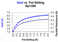
Yes, except in your new supply switching the meter range will also limit the supply adjust range to about 6V. You need to decide if having a nonlinear adjust response on the 6V range is acceptable. The first half of the pot will give you 1.25-5.5V, the second half will give about 0.5V. I'll post a schematic and 6V adjust response later; unless someone beats me to it...
 

AnalogKid

Joined Aug 1, 2013
12,174
Actually, changing the switch so it adjusts the adjustment range as well as the displayed range is an option. As above, if the meter (and adjustment range) were satisfactory before, no need to complicate things at this time. Once the new regulator circuit is debugged and running, modifying it to fiddle around with the ranges is a minor tweak since you already have a case with a switch and pot.

ak
 

Thread Starter

PrincessWoona

Joined Nov 30, 2015
53
Keep that in mind when you assemble the project. A higher current transformer will be larger. You should research approximate dimensions before you start mounting things.
Aside from the regulator, you may already have all the parts you need.
Use the existing resistor. It will be no less, or more, accurate than before. If you find it isn't good enough, you can address later. And you should breadboard (solderlessly) so you can test and make any changes more easily.
Yes, except in your new supply switching the meter range will also limit the supply adjust range to about 6V. You need to decide if having a nonlinear adjust response on the 6V range is acceptable. The first half of the pot will give you 1.25-5.5V, the second half will give about 0.5V. I'll post a schematic and 6V adjust response later; unless someone beats me to it...
The nonlinear is just fine. I just need a schematic and parts. Thanks for helping. I may put one of my small 2k potentiometers in there for the meter so I can adjust it to as close as possible. It doesn't need be 100% but my OCD will want to make it.
 

dl324

Joined Mar 30, 2015
18,403
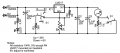
My schematic editor didn't have a transformer symbol. Connect the center tap to ground and the other ends to either rectifier diode.
upload_2015-12-6_8-38-45.png
Wire the fuse as it is currently. You need to add a switch to the transformer primary. The neon indicator has been replaced with LED1.

EDIT: I forgot to include a ground symbol; that's the bottom net. The transformer centertap will be connected to that net. Output is between ground and the top of the meter connection...

When wiring the LM317, note that the tab (or case, depending on package you use) is the output voltage. If the heatsink is grounded, you'll require isolation. I'd use a TO-220 package.
 
Last edited:

AnalogKid

Joined Aug 1, 2013
12,174
dl324 and I have different experience bases, which of course leads to different recommendations. From the "if it ain't broke" department:

The input circuit (line cord, neon indicator, noise filter capacitor, transformer primary) are fine as they are.

So are the meter and its range-setting resistor and switch.

Increase the diodes to ones with a forward current rating of at least 2 A (3 A is better) for the LM317 and 5A (6 A is better) for the LM350. It might be cheaper to buy a diode bridge and use half of it.

You already have two sets of insulating mounting hardware for the TO-3 package, so I recommend you get your new regulator in the same package and reuse what you have. With two sets you should be able to harvest one good set.

I hate shotgun maintenance, but in this case - replace C2, the big orange electrolytic cap. It was old when you were young.

ak
 

RichardO

Joined May 4, 2013
2,270
One more thought. Check that the unloaded voltage at the output of the rectifier and filter is not too high for the regulator you choose.

For instance, the LM317 is rated for 40 volts absolute maximum. And, the LM350 only is rated for 35 volts absolute maximum.
 

dl324

Joined Mar 30, 2015
18,403
I thought about reusing the neon indicator, but the power switch is part of the dual gang pot. Not having a good feel for the OP's capabilities, I opted to put the indicator on low voltage.

I thought about the 1N4004 current limit, but figured the safety margin built in for the 1A spec would be "good enough" considering that the original transformer is being used. Reverse voltage rating is overkill, but that was the default 1N400x diode in Eagle and I was too lazy to change it to something lower. 1A seems to be the sweetspot pricewise and that seems important.

Price also prompted my recommendation for TO-220 over TO-3.

Using different capacitor values precluded reusing the existing ones...
 
Last edited:

Thread Starter

PrincessWoona

Joined Nov 30, 2015
53
My schematic editor didn't have a transformer symbol. Connect the center tap to ground and the other ends to either rectifier diode.
View attachment 96012
Wire the fuse as it is currently. You need to add a switch to the transformer primary. The neon indicator has been replaced with LED1.

EDIT: I forgot to include a ground symbol; that's the bottom net. The transformer centertap will be connected to that net. Output is between ground and the top of the meter connection...

When wiring the LM317, note that the tab (or case, depending on package you use) is the output voltage. If the heatsink is grounded, you'll require isolation. I'd use a TO-220 package.
Looks good. As for r3, I don't have a 390ohm resistor. I only have carbon comp resistors(for vintage items). Could it be replaced with a close value or do I need to many resistors together to get the value? So for r3 and that switch it just removes the resistor for 30v and puts it in for 6v? And what's up with B and B1? If the bottom lines the negative then won't the led limit current massively? Unless there's something I'm missing. I'll look online to see I can get a 390 and 82 ohm resistor.
 

dl324

Joined Mar 30, 2015
18,403
I don't have a 390ohm resistor. I only have carbon comp resistors(for vintage items). Could it be replaced with a close value or do I need to many resistors together to get the value?
That resistor sets the maximum for the 6V range. You can use any resistor or combination of resistors you have handy. The closer you get to 390, the closer you'll get to 6V max.
So for r3 and that switch it just removes the resistor for 30v and puts it in for 6v?
That's it. Putting 390Ω in parallel with the 2K pot gives a smaller, nonlinear adjust range.
And what's up with B and B1?
Artifacts from the symbol I used in Eagle. I can remove them if I make a revision.
If the bottom lines the negative then won't the led limit current massively? Unless there's something I'm missing.
Depending on the filtered transformer output, the LED should be limited to around 15mA. Anything under 20mA would be okay.
I'll look online to see I can get a 390 and 82 ohm resistor.
Since cost seems to be important, just use what you have. The 82Ω resistor sets the adjust current. If you use something close, it will change the maximum output voltage.

I don't know if you have any electronics surplus stores nearby. The parts are common (unless you go for LM317K).
 

Thread Starter

PrincessWoona

Joined Nov 30, 2015
53
I thought about reusing the neon indicator, but the power switch is part of the dual gang pot. Not having a good feel for the OP's capabilities, I opted to put the indicator on low voltage.

I thought about the 1N4004 current limit, but figured the safety margin built in for the 1A spec would be "good enough" considering that the original transformer is being used. Reverse voltage rating is overkill, but that was the default 1N400x diode in Eagle and I was too lazy to change it to something lower. 1A seems to be the sweetspot pricewise and that seems important.

Price also prompted my recommendation for TO-220 over TO-3.

Using different capacitor values precluded reusing the existing ones...
As for the neon light I'll just replace. I used one before but it was much dimmer then a led(the leads broke off it shortly after installing. It was a high stress area in a high capacitor reformer I did awhile back. Replaced with an led). So I'll prefer the brighter led. As for capability I have only been into electronics for the last year or so. I'm taking a electronics course and still learning a lot. I'm more into vintage electronics(60's or sooner).
 
Top