Facebook
 Google
 GitHub
 Linkedin
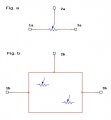
Hi, I'm new to circuit design and need some help solving what seems a simple puzzle: I need 2 potentiometers to act as one.
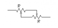
The closest I got was this:

But this will not do the work because it would only have to pins (acting like a variable resistor rather than a potentiometer). What I need is the 2 potentiometers combined together and connected to 3 wires, which will give me the total resistance when adding the result from the 2 first wires + the last 2 wires (like a single potentiometer).
Can anyone please help?
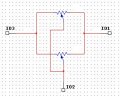
The closest I got was this:
But this will not do the work because it would only have to pins (acting like a variable resistor rather than a potentiometer). What I need is the 2 potentiometers combined together and connected to 3 wires, which will give me the total resistance when adding the result from the 2 first wires + the last 2 wires (like a single potentiometer).
Can anyone please help?
Attachments
-
 30.5 KB Views: 144

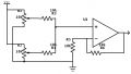
 If you can explain what you are trying to accomplish with this odd circuit, then perhaps we could come up with some better solutions.