LM324 Operational Amplifier Circuit

Thread Starter

cevval

Joined Dec 6, 2011
63
In my project, I want to achieve relays to be on and off at different reference voltage levels when an analog voltage signal input from 0.0V to + 2.0V is applied to the inputs of LM324 IC. When the inputs returns back to levels less than the ref voltages, the related relay comes to off state again.
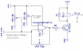
Please see attached diagram which is a part of a LM324 Opamp circuit.
My question is: When input voltage reaches the reference voltage, relay works with chattering and this contiues if the input voltage stays same as the ref voltage, which may really happen in real life, but, when it goes beyond above the ref voltage chattering stops any way. This could be a hysterisis problem. I want to avoid this chattering problem.
How I can solve this problem. Please, somebody can help me.
Regards, good fellows.
Cevval of yours.
 

Attachments

Ron H

Joined Apr 14, 2005
7,063
One potential problem is that your base resistor R8 is too large. This can cause chattering. How much current does the relay require? You should select R8 such that Ib≈Ic/10. Keep in mind that this resistor will have ≈7V across it when the op amp output is high.
You can add hysteresis with a resistive voltage divider between op amp output and Vin, with the divider output going to the +in pin. As an example, if you add 1Meg from output to +in, and 10k from +in to Vin, you will get about
Vout*10k/(1Meg+10k) ≈ 75mV of hysteresis.
 

Thread Starter

cevval

Joined Dec 6, 2011
63
One potential problem is that your base resistor R8 is too large. This can cause chattering. How much current does the relay require? You should select R8 such that Ib≈Ic/10. Keep in mind that this resistor will have ≈7V across it when the op amp output is high.
You can add hysteresis with a resistive voltage divider between op amp output and Vin, with the divider output going to the +in pin. As an example, if you add 1Meg from output to +in, and 10k from +in to Vin, you will get about
Vout*10k/(1Meg+10k) ≈ 75mV of hysteresis.
First of all, Thank you very much for your quick response.
I tried the first proposal. Relay coil is 280Ω (I measured) and it draws 43mA by my calculation. So the base resistor calculated to be 9V/43mA= 2.1kΩ. I tried 2.2kΩ. Problem continued.
Now, I will try the second proposal. But first I will revise my diagram and post it later to see whether understand your proposal correctly or not.
Regards.
 

Thread Starter

cevval

Joined Dec 6, 2011
63
One potential problem is that your base resistor R8 is too large. This can cause chattering. How much current does the relay require? You should select R8 such that Ib≈Ic/10. Keep in mind that this resistor will have ≈7V across it when the op amp output is high.
You can add hysteresis with a resistive voltage divider between op amp output and Vin, with the divider output going to the +in pin. As an example, if you add 1Meg from output to +in, and 10k from +in to Vin, you will get about
Vout*10k/(1Meg+10k) ≈ 75mV of hysteresis.
Dear Ron,
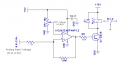
Please, see my attached revised diagram. Is my understanding right, Please confirm. So, I go to shop and buy the voltage dividers. Thanks.
 

Attachments

SgtWookie

Joined Jul 17, 2007
22,230
I've extracted your schematic from the .pdf and posted it in .png format; this is preferable because one doesn't have to download anything in order to view the schematic. Additionally, .png format files are very compact, and are not "lossy" like .jpg/.jpeg format files.


Attachments

Ron H

Joined Apr 14, 2005
7,063
First of all, Thank you very much for your quick response.
I tried the first proposal. Relay coil is 280Ω (I measured) and it draws 43mA by my calculation. So the base resistor calculated to be 9V/43mA= 2.1kΩ. I tried 2.2kΩ. Problem continued.
Now, I will try the second proposal. But first I will revise my diagram and post it later to see whether understand your proposal correctly or not.
Regards.
.
You need Ib=4.3mA, but your base resistor will only have about 6.8V across it, because Vbe≈0.8V, and the LM324 output will only go to about 7.6V, even with a fresh 9V battery.
Rb=6.8V/4.3mA≈1.6kΩ. Having said that, 2.2k would probably work.
You misinterpreted the term "voltage divider". See the attached schematic.
You can change the hysteresis by changing either the 10k or the 1Meg resistor.
 

Attachments

Thread Starter

cevval

Joined Dec 6, 2011
63
.
You need Ib=4.3mA, but your base resistor will only have about 6.8V across it, because Vbe≈0.8V, and the LM324 output will only go to about 7.6V, even with a fresh 9V battery.
Rb=6.8V/4.3mA≈1.6kΩ. Having said that, 2.2k would probably work.
You misinterpreted the term "voltage divider". See the attached schematic.
You can change the hysteresis by changing either the 10k or the 1Meg resistor.
Dear Mr Ron,
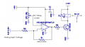
Your proposal worked very well as attached diagram. Thank you very much for your valuable interest on my subject problem.
Regards
 

Attachments

Reloadron

Joined Jan 15, 2015
7,977
Odd, showed up in new posts list, or so I think.

It definitely is old.....:)

Regards, Dana.
That it did and because post #8 revived it and once revived the last post will cause it to show up. Not to say it's a bad thing but I figure the original poster or thread starter won't likely be back. :)

Ron
 
Top