 Facebook
 Google
 GitHub
 Linkedin
First off I hope ive posted this in the right section.
I am having a little trouble determining the connections of this simple AC alternator. This is the stator and a rotating rotor with magnets spins inside producing AC current. There is no field coils or brushes.
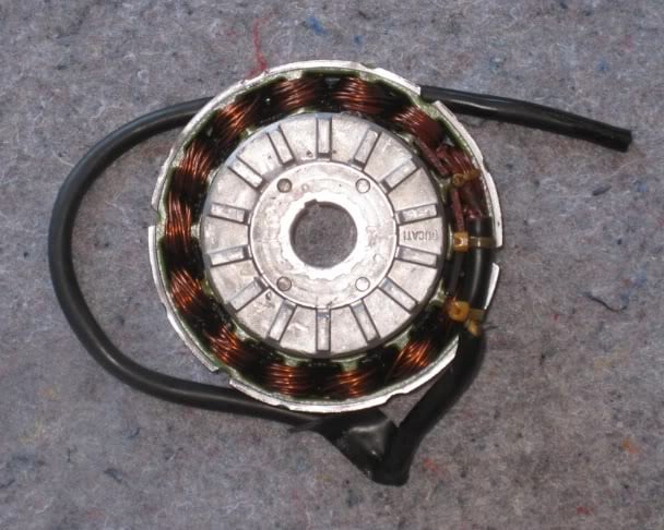
This stator has 3 wires, 2 yellow and 1 red and Im let to believe that there is 2 separate circuits/coils/windings and that one end of each winding is connected together to the red wire which is a center tap I have shown this in my drawing A. The information I can seem to find on this alternator is suggesting that the 2 circuits are out of phase and the output on each yellow wire is not in synch and the 2 can not be connected together. I dont know if that makes sense to you at all. I have also heard that the voltage between one yellow and one red center tap wire is 35 volts AC but you cant just use the second yellow wire to get the full 70volts as the second one will cancel the other one out? The only thing is that when ive heard this people have been discussing connecting it to a regulator rectifier and converting to DC and not AC.
When in AC there is supposed to be 90 watts on each separate yellow wire if you wire each on to a separate AC regulator and keep the circuits separate. I was told that if you connect 1 yellow and one red wire and leave one yellow unplugged, you can get 150-160 watts (not sure if they really mean 180W). But this does not make sense if the red wire is a center tap as essentially your not getting the output from the second winding so I believe I was given wrong information here.
I have shown in diagrams B and C 2 ways I thought I could connect it to a AC regulator in series or parallel, but since Im led to believe the stator is out of phase Im dont think this would work combining both circuits together like this in series or parallel and I dont think sure I would get the full output together? If this wont work then I believe I need to make the alternator in phase
As I understand it, having different phases is due to having the coils wound in different directions (CCW, CW) to the others??? There is 14 poles so I assume 7 are wound CCW and 7 CW and this makes the 2 circuits of 7 wound poles produce the power in 2 phases?
Anyway, what I want to do is get the full 70 volts which is ment to equal somewhere from 150-180 watts when regulated to (12-15 voltes AC), out of the alternator at the one time. To do this I think it has to be converted so the 2 circuits are in phase but Im really not sure. Now I reckon what I need to do is to basically flip the connections of one of the windings around. I have shown this in diagram D I have left a little bit of red and yellow on each end of one of the windings so you can see I have swapped that windings connections around. If I am correct, I have now converted this to producing the full 70 volts in phase?? Im not really sure though as the wires would still be wound the same on the poles, its just that Ive changed which end is attached to the yellow lead and which is connected to the red lead.
Assuming ive now got the 2 circuits working in one phase, now one way to connect it would be in series as shown in diagram E. One yellow to ground and the other into the AC regulator and the red wire is not connected.
The second way is to connect it in parallel as shown in diagram F.
Now I always believed that connecting 2 coils or windings in parallel will give you the most output but Im not really sure. The big question is, which way is going to give me the most power series or parallel?
I have tried searching the web, wikipedia etc for this sort of stuff but can never seem to find anything that simply answers my question exactly in an easy to understand way. I just want to finally know once and for all how this works! I will keep trying to look though.
Thanks for your help.

I am having a little trouble determining the connections of this simple AC alternator. This is the stator and a rotating rotor with magnets spins inside producing AC current. There is no field coils or brushes.
This stator has 3 wires, 2 yellow and 1 red and Im let to believe that there is 2 separate circuits/coils/windings and that one end of each winding is connected together to the red wire which is a center tap I have shown this in my drawing A. The information I can seem to find on this alternator is suggesting that the 2 circuits are out of phase and the output on each yellow wire is not in synch and the 2 can not be connected together. I dont know if that makes sense to you at all. I have also heard that the voltage between one yellow and one red center tap wire is 35 volts AC but you cant just use the second yellow wire to get the full 70volts as the second one will cancel the other one out? The only thing is that when ive heard this people have been discussing connecting it to a regulator rectifier and converting to DC and not AC.
When in AC there is supposed to be 90 watts on each separate yellow wire if you wire each on to a separate AC regulator and keep the circuits separate. I was told that if you connect 1 yellow and one red wire and leave one yellow unplugged, you can get 150-160 watts (not sure if they really mean 180W). But this does not make sense if the red wire is a center tap as essentially your not getting the output from the second winding so I believe I was given wrong information here.
I have shown in diagrams B and C 2 ways I thought I could connect it to a AC regulator in series or parallel, but since Im led to believe the stator is out of phase Im dont think this would work combining both circuits together like this in series or parallel and I dont think sure I would get the full output together? If this wont work then I believe I need to make the alternator in phase
As I understand it, having different phases is due to having the coils wound in different directions (CCW, CW) to the others??? There is 14 poles so I assume 7 are wound CCW and 7 CW and this makes the 2 circuits of 7 wound poles produce the power in 2 phases?
Anyway, what I want to do is get the full 70 volts which is ment to equal somewhere from 150-180 watts when regulated to (12-15 voltes AC), out of the alternator at the one time. To do this I think it has to be converted so the 2 circuits are in phase but Im really not sure. Now I reckon what I need to do is to basically flip the connections of one of the windings around. I have shown this in diagram D I have left a little bit of red and yellow on each end of one of the windings so you can see I have swapped that windings connections around. If I am correct, I have now converted this to producing the full 70 volts in phase?? Im not really sure though as the wires would still be wound the same on the poles, its just that Ive changed which end is attached to the yellow lead and which is connected to the red lead.
Assuming ive now got the 2 circuits working in one phase, now one way to connect it would be in series as shown in diagram E. One yellow to ground and the other into the AC regulator and the red wire is not connected.
The second way is to connect it in parallel as shown in diagram F.
Now I always believed that connecting 2 coils or windings in parallel will give you the most output but Im not really sure. The big question is, which way is going to give me the most power series or parallel?
I have tried searching the web, wikipedia etc for this sort of stuff but can never seem to find anything that simply answers my question exactly in an easy to understand way. I just want to finally know once and for all how this works! I will keep trying to look though.
Thanks for your help.


