need help understanding how digital sine wave circuit works

Thread Starter

count_volta

Joined Feb 4, 2009
435
Hi, I need help understanding how a circuit works. The circuit below.


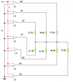
This is a Johnson counter made with a 74hc4015 shift register. I understand how the Johnson counter works. But this circuit is supposed to create a digital staircase sine wave. It is a digital sine wave generator.

What I don't understand is how the resistors at the different Q outputs which are all tied together play a role in the digital sine wave generation. I mean the resistors are not grounded. No current is flowing through them. What exactly do they do? If no current is flowing through the resistors its the same as not having them there at all, at least I always understood that to be the case.

I know the Johnson counter creates the following outputs at Q0-Q7.

00000000 10000000 11000000 11100000 11110000 11111000 11111100 11111110 11111111 01111111 00111111 00011111, and so on....

Each of these voltages will be around 3V or so. But what the heck do the resistors do?

Can someone help me out please. Thanks.
 
Last edited:

Jony130

Joined Feb 17, 2009
5,488
It's voltage divider.
Think about 1 as a connection to Vcc and 0 to GND.
An 4015 in not a Johanson counter. 4015 is a shift register
 

Thread Starter

count_volta

Joined Feb 4, 2009
435
It's voltage divider.
Think about 1 as a connection to Vcc and 0 to GND.
An 4015 in not a Johanson counter. 4015 is a shift register
Then wouldn't the resistors actually be in parallel not series? You say its a voltage divider (in which resistors are in series)

Like for example if q0q1q2 = 1 1 1 and the rest of the outputs are 0, that means the 57.6k, 30.9k,23.7k are in parallel and have 3 volts applied at the top, and they are all connected at the bottom?

If its not too much trouble could you draw an equivalent circuit for me in this situation?

Yes a 4015 is not a Johnson counter, but the configuration in which its connected is a Johnson counter.
 

beenthere

Joined Apr 20, 2004
15,819
If you take the output to ground through a resistor (about 100K at a guess) to ground, the several outputs will act as current sources and the resistors will act to weight each one differently (think of it as an R not-quite 2R ladder). The summed voltage at the output will somewhat resemble a sine wave. You will need an op amp to buffer that voltage in order to make use of it.

Because the clock intervals do not vary, the voltage step with each one has to be different to approximate the differing slope of a sine waveform as seen at regular time intervals.
 
Last edited:

Jony130

Joined Feb 17, 2009
5,488
Like for example if q0q1q2 = 1 1 1 and the rest of the outputs are 0, that means the 57.6k, 30.9k,23.7k are in parallel and have 3 volts applied at the top, and they are all connected at the bottom?

If its not too much trouble could you draw an equivalent circuit for me in this situation?
Yep here you have:
 

Attachments

Thread Starter

count_volta

Joined Feb 4, 2009
435
Thanks guys, I think I understand. What is weird to me, and what I never thought about before is 0V (which I know is equivalent to ground) means that current will flow from the higher voltage towards ground, even if its not a literal battery (power supply).

I mean whats weird is, I don't see the other side of the battery. Its connected to the chip. So current actually flows into the shift register chip. That is so weird to me for some reason.

Okay, can I always assume that if I have a digital chip, and one of my outputs is a "0" (0 volts) and I have a "1" (5 volts), and if I connect the output that has the "1" to the output that has the "0", current will flow as if though the "1" output is the positive side of the battery, and the "0" output is the negative side of the battery?

Btw I built the circuit and here is my output from the oscilloscope. Ain't it pretty? The bottom waveform is the clock.

 
Last edited:

Jony130

Joined Feb 17, 2009
5,488
Thanks guys, I think I understand. What is weird to me, and what I never thought about before is 0V (which I know is equivalent to ground) means that current will flow from the higher voltage towards ground, even if its not a literal battery (power supply).
I mean whats weird is, I don't see the other side of the battery. Its connected to the chip. So current actually flows into the shift register chip. That is so weird to me for some reason.
All Integrated circuits need external power supply connection.
For example for 4015 you need connect pin 16 to positive terminal of a power supply and pin 8 to negative terminal of a power supply.

And now if we get 4069 inverter (NOT) gate and connect input node to positive terminal of a power supply.
So we have input at "high," or in a binary "1" state and the output is in "low" state or binary "0".


So output of a gate is sink current to provide a "0" or "low" state.
Vout is almost equal GND.

And now see what happens if we reverse the input's logic level to a binary "0", "low".
The output now must be in "High" binary "1" state.
So output of a gate is sourcing the output current.
And output voltage is almost equal VDD.


Okay, can I always assume that if I have a digital chip, and one of my outputs is a "0" (0 volts) and I have a "1" (5 volts), and if I connect the output that has the "1" to the output that has the "0", current will flow as if though the "1" output is the positive side of the battery, and the "0" output is the negative side of the battery?
Yes, but you must never connect two outputs of a digital chip together.
Becaues then you will have a short in the circuit.

PS. And you have to remember that real CMOS 4000 series circuit has limited output current ability.
http://www.iele.polsl.pl/elenota/Texas_Instruments/schs054.pdf
 
Last edited:

Potato Pudding

Joined Jun 11, 2010
688
Yes, but you must never connect two outputs of a digital chip together.
Becaues then you will have a short in the circuit.
Many chips have built in protection against shorting - like internal resistors on the ouput and people with less experience don't always realize what kind of problem they have set up a problem in their circuit because they just get a bad output signal. The shorted output drops low on a 1 or goes high on a 0 because of the drop across the internal protection and they think their IC is bad.

: ) It is better than the chips going pop! and Smoke$$$

It was a good point made that you can't connect outputs directly together- whether the chip has been designed for a short tolerance or not. Rubbishing your output levels or the chip; neither is what anyone would want.
 
Top