 Facebook
 Google
 GitHub
 Linkedin
Greetings everybody,
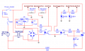
I am experiencing an issue with the zero-crossing detector, I use a 4N35 to send a signal to my arduino at every zero crossing of the AC to control a load, the issue is everything works 100% fine while the arduino is wired to my PC, but once I disconnect the USB and instead use the 5V supply I have to power the arduino the zero-crossing detector doesn't seem to work, I don't have an oscilloscope to check the pulse but with a multimeter i get abnormal voltage between the ZCD pin and ground flickering between 350mV to 450mV while when it's plugged in I get a steady 500mV and does trigger the triac as it should, so could the supply be bad? it does output 4.85V DC but I noticed it also outputs 400mV AC despite having the smoothing capacitors.
It's also worth mentionning the arduino seems to power on properly on the 7805 supply, I can still trigger the triac but I get nothing from the zero-crossing detector however.
Schematic information:
U1 = 4N35 U2 = MOC3021 U3 = 7805
It's worth mentionning I have added a diode before R1 to separate the 120Hz unfiltered signal from the powersupply or else it wouldn't work, I also removed R11.
Attachments
-
![thumbnail_c7932e17f80a4661710c44a4744d69b6[1].png](/data/attachments/159/159252-c7932e17f80a4661710c44a4744d69b6.jpg) 6.7 KB Views: 63
6.7 KB Views: 63 -
 84.3 KB Views: 67


