Hi,
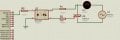
I want to use a zero crossing detector on my projet, i need help about the value of R1,R2 so i cant dammage the bridge (2W04G) and the optocoupleur(4n25).Im new to electronics so i have some issues on reading datasheet.
As the maximum IR emitter current rating is 80 mA I suggest limiting the current to about half this value. So R = 230/0.04 ohms = 5750 ohms. This will be the sum of the two resistor values. So making each resistor 2.7K should be about right. The total power dissipation in the two resistors will be 230 ^2/5400 = 9.8 watts. So each resistor will dissipate about 5 watts. I would choose resistors with 10 watts rating. The forward voltage of the IR emitter can be ignored.
As the maximum IR emitter current rating is 80 mA I suggest limiting the current to about half this value. So R = 230/0.04 ohms = 5750 ohms. This will be the sum of the two resistor values. So making each resistor 2.7K should be about right. The total power dissipation in the two resistors will be 230 ^2/5400 = 9.8 watts. So each resistor will dissipate about 5 watts. I would choose resistors with 10 watts rating. The forward voltage of the IR emitter can be ignored.
Hi Dick, I agree. I chose the high current so that the zero crossing pulse would be as short as possible with that design of detector. Like many request for help we are not given the full picture. Depending on the TS's requirement it may be possible to use higher value resistors. (Or a different design of zero crossing detector may be a better solution.)
The transistor in the opto only needs to be able to sink 0.5mA (5V, 10k) and from the datasheet a diode current of 10mA should be sufficient and that makes the resistors 12k and the power in each would be 1.2W.
Hi Albert, As the minimum transfer ratio is 20 % then you would only need 2.5 mA through the IR diode for the photo transistor to sink 0.5 mA As the peak voltage of 230 volts RMS is about 325 volts the peak current current with 24K would be about 13 mA 2.5/13 = 0.19 so SIN^-1 of 0.19 is about 11 Deg. So the transistor would not be fully conducting fo about 11 degrees either side of the zero crossing. The TS will have to decide if this is enough for his requirement. Even the values I chose may not give a short enough zero crossing pulse for the TS.
Diodes and iR-LED have junction capacitance + Opto (the transistor inside the) has also a storage time = in conjunction with limiting resistors they add to the delay of your thing . . . with the given opto you can pre bias the output transistor . . . however the optos can be used as photodiodes . . . https://www.vishay.com/docs/83590/fastswit.pdf -or- https://www.vishay.com/docs/83604/6n135.pdf
Hi Dick, I agree. I chose the high current so that the zero crossing pulse would be as short as possible with that design of detector. Like many request for help we are not given the full picture. Depending on the TS's requirement it may be possible to use higher value resistors. (Or a different design of zero crossing detector may be a better solution.)
Perhaps it would be better if we advised ANOUXR to use a different optocoupler or a different circuit (perhaps at ci139 suggests) if he wants to get by with a lower power dissipation.
Dimming an halogen lamp usually does not require a lot of timing precision.
I believe we do.
And I have to throw in an LTspice simulation of the basic circuit (with some altered part's values due to model availability).
The total average power dissipation is about 200mW.
That Precision Zero Cross Detector circuit you referenced was originally designed by Christian de Godzinsky (whom I talked with regarding that very circuit in 2015) from Finland and published in EDN. Free to use. Here is the original article:
I don't think anyone has said it, but dimming a halogen lamp is not a good idea. Halogens need to operate a full power to produce the heat necessary to maintain the halogen cycle. Lower power will darken the glass and shorten the lamps life. Dimming halogens
 Facebook
 Google
 GitHub
 Linkedin