 Facebook
 Google
 GitHub
 Linkedin
Deal all,
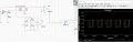
I'm trying to build a power factor measure with zero cross detection with LM 358 and a XOR gate but I'm lacking of electronic knowledge.
I already build the circuit as attached and stuck with some problems.
1) On the current side when the sine wave cross to the negative site it gives me an output on the Op-Amp, so I decided to put a diode to filter this negative part (see attachment "Circuit without diode").
2) I used the first diode that the simulator gave me 1BH62. The signal is perfect at the XOR gate (see attachment "Circuit with diode") and I can calculate the time and then get the power factor but I want to use some commercial diode like 1N4149 and it gave me no result for the current (see attachment "Circuit with 1N4149.)
3) I tried to put a pararel resistor with the value of 1k and it gave me a signal like a Ripple effect and it gave some difference between the signals (see attachment "Circuit with 1N4149_Resistor")
That said I'm out of options for what should I do since my knowledge about electronics is not something high. I don't want to simulate it with any value that give me a result because I need to build a prototype of my simulation.
Kind Regards,
Daniel Oliveira Barbosa
Attachments
-
 146.1 KB Views: 31
 -
 145.7 KB Views: 28
 -
 149.4 KB Views: 24
 -
 144.6 KB Views: 24


