Xtal unstable

Thread Starter

FroceMaster

Joined Jan 28, 2012
708
Hi
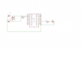
Have this simpel setup. , see attached schematic.
The problem is that it will only Work, when i put my finger in near of the xtal ( not touch )
When it then runs, it runs to slow.
ex 60 times at 1 sec each gives 1 minut, but it takes 77 seconds to do it in real seconds.

here is the code
i use a 16F1509 microchip.


Code:
#include <htc.h>
#include <stdio.h>
#include <stdlib.h>
#include "lcd.h"
#include <string.h>

#pragma config FOSC = LP  // Oscillator Selection Bits (XT Oscillator, Crystal/resonator connected between OSC1 and OSC2 pins)
#pragma config WDTE = OFF  // Watchdog Timer Enable (WDT disabled)
#pragma config PWRTE = ON  // Power-up Timer Enable (PWRT disabled)
#pragma config MCLRE = OFF  // MCLR Pin Function Select (MCLR/VPP pin function is digital input)
#pragma config CP = OFF  // Flash Program Memory Code Protection (Program memory code protection is disabled)
#pragma config BOREN = OFF  // Brown-out Reset Enable (Brown-out Reset enabled)
#pragma config CLKOUTEN = OFF  // Clock Out Enable (CLKOUT function is disabled. I/O or oscillator function on the CLKOUT pin)
#pragma config IESO = OFF  // Internal/External Switchover Mode (Internal/External Switchover Mode is enabled)
#pragma config FCMEN = ON  // Fail-Safe Clock Monitor Enable (Fail-Safe Clock Monitor is enabled)

// CONFIG2
#pragma config WRT = OFF  // Flash Memory Self-Write Protection (Write protection off)
#pragma config STVREN = ON  // Stack Overflow/Underflow Reset Enable (Stack Overflow or Underflow will cause a Reset)
#pragma config BORV = LO  // Brown-out Reset Voltage Selection (Brown-out Reset Voltage (Vbor), low trip point selected.)
#pragma config LPBOR = OFF  // Low-Power Brown Out Reset (Low-Power BOR is disabled)
#pragma config LVP = ON  // Low-Voltage Programming Enable (Low-voltage programming enabled)

#define _XTAL_FREQ 16000000
#define FOSC 16000000L

#define set_hour RB4 //Buttons
#define set_minut RC2
#define set_week RC1
#define set_time RC3

bit sec;
int secund;
char test[10];


static void interrupt isr(void)  // Here is interrupt function - the name is unimportant.
{
 if(TMR1IF) 
 TMR1L=0x00; 
 TMR1H=0x80; 
 TMR1IF=0;
 sec=1;
 RA2=!RA2;
}

void setup (void)
{

IRCF0=1; //16 mhz
IRCF1=1;
IRCF2=1;
IRCF3=1;
SCS0=0; // osc til 1 sec
SCS1=0;
 TRISA=0; //set all port out
 TRISA2=0; // set port 2 ind
 TRISA4=1; // set port 4 ind.
 TRISA5=1; // set port 5 ind.
 TRISB4=1; // port B 4 in 
 TRISB5=1; // port b 5 in
 TRISB6=0; // b6 ud
 TRISB7=1; // port b7 in
TRISC0=0;
TRISC1=1;
TRISC2=1;
TRISC3=1;
TRISC4=0;
TRISC5=0;
TRISC6=0;
TRISC7=0;

TMR1CS0=0;
TMR1CS1=1;
T1OSCEN=1;

 GIE = 0;  // Global interrupt disable just in case
 //ANSELA = 0b00000001;  // Set PORT AN0 to analog input AN1 to AN7 digital I/O
 ANSELA=0; // set alle digital. 
 ANSELB=0;
 ANSELC=0;//turn off all analog functions
 lcd_init();
 T1CKPS1=0;
 T1CKPS0=0;
}

void main (void)
{
setup();  //do the setup
  lcd_clear();
  lcd_goto(0x00);
  lcd_puts("1234567890abcdefghij");
  lcd_goto(0x40);
  lcd_puts("abcdefghij1234567890");
  
  __delay_ms(1000);
  lcd_clear();
  TMR1L=0x00; 
  TMR1H=0x80; 
  TMR1ON=1; // turn on timer1
  sec=0;
  PEIE=1;
  TMR1IE=1;
  TMR1GE=1;
  GIE=1;
lcd_goto(0x00);

  while (1)
  {
  if (sec==1)
  {
  secund++;
  //if (secund==60) secund =0
  itoa(test, secund, 10);
  lcd_goto(0x01);
  
  lcd_puts(test);//*/
  sec=0;
  }


  }
}
 

Attachments

JSCV

Joined Oct 3, 2015
23
Hello FroceMaster,

Your schematics show as nerdegutta says R1, This can be removed unless you have some special reason to put it there.
For the capacitors, you need to check the datasheet of the oscillator and make sure you use the correct value.
Also make sure the oscillator circuit is as close to the micro controller as possible with a short route to ground.

For your code i see :
#define _XTAL_FREQ 1600000
#define FOSC 16000000L
You define your oscillator is running at 16mhz however in your schematic you use an oscillator of 32.768kHz ? (No units mentioned)
 

Thread Starter

FroceMaster

Joined Jan 28, 2012
708
Re R1, i heard from other that i should use the resistor.

The _XTAL_FREQ should be the xtal of the internal clock, as far as i know.
These 2 lines have always been in my project, and have worked so far.
 

Attachments

JSCV

Joined Oct 3, 2015
23
Hello FroceMaster,

I see i made a mistake interpreting your schematic and code, you are using the internal oscillator.
So please forget the last part of the post, You can refer to page 53 of the datasheet for more details on using crystal oscillator.
I think the most important thing is to get the oscillator running properly before troubleshooting any further.

Schematics in data sheet :
upload_2015-10-4_20-27-24.png
 

bertus

Joined Apr 5, 2008
22,923
Hello,

Sometimes resistors are used on xtal oscillators.
The one in series with the gate has a much lower value as in your schematic:

xtal_oscillator_using_gates.png

Bertus
 

Thread Starter

FroceMaster

Joined Jan 28, 2012
708
the xtal extrern is for use to a 1 sec . to use in Watch to tell the time,
could i do a simple circiut that came with a 1 minut impuls i would be better.
 

nerdegutta

Joined Dec 15, 2009
2,689
C:
#pragma config FOSC = LP  // Oscillator Selection Bits (XT Oscillator, Crystal/resonator connected between OSC1 and OSC2 pins
This code tells the MCU you are using a Low Power crystal or resonator on OSC1 and OSC2.


C:
#define _XTAL_FREQ 16000000
This code line tells the compiler to use 16MHz. Used for __delay_ms and such.

Am I right or wrong?
 

JSCV

Joined Oct 3, 2015
23
Depending on the precision you require you could choose to run the counter off the internal 16mHz(1%) clock using a internal prescaler, this would eliminate any off the external circuitry used for driving the timer/counter.
 

Thread Starter

FroceMaster

Joined Jan 28, 2012
708
sure i can, but but, if i get ex 2 MHz FOSC=500 KHz, that will give at 16 bit = 65535, and prescale 1:8 is 524280
by selecting value "F424" to timer1 the overflow should happens at 62500 * 8 = 500.000 and that should be 1 second.

Have now written this, but now it Count very fast but unstable, with no x-tal
 

JSCV

Joined Oct 3, 2015
23
Please

I cant see the code you have written but you should use timer 2, since your internal clock is 16MHZ, Timer 1 will give you an interrupt much quicker than you expected.

If you use timer 2 with max prescaling(64) it will be : 16 MHz / 4 / 64 = F424
 
Last edited:

dannyf

Joined Sep 13, 2015
2,197
see attached schematic.
You will need to check the datasheet to see what kind of connections it needs to run the LP oscillator. Those oscillators tend to have low gain so putting a serial resistor there further reduces the gain -> could be why yours isn't oscillating.

Cant use that.
Your code is simply using the timer to advance time, in a quite imprecise way -> if you meant it to be an RTC, it is implemented incorrectly.

You can replicate the same by running the chip on other timers. For example, 16Mhz oscillator -> 4Mhz Fosc, at 1:64 prescaler, 31250 count -> 0.5 second per roll-over.

Pretty nice for an RTC + blink generator.

31250 count
If you have a 8-bit counter, you can then use a 250 count period, and every 125 isr = 0.5 second.

Same concept, different math.
 

JohnInTX

Joined Jun 26, 2012
4,787
Microchip's AN849 has all you need to know about a PIC oscillator and how and when to choose the R/C components.

As the others have said, getting the period right is mostly a matter of counting clocks once the osc is running.
@nerdegutta 's point is valid. 16MHz is unlikely to run well with a LP oscillator config setting..
 

Thread Starter

FroceMaster

Joined Jan 28, 2012
708
Correct me if iam wrong.
If i set 2 MHz, then FOSC = 500 kHz.
Prescale 1:64
TMR2 rollover at 245
Postscale 1:16
Then i give a 1 sec periode ?
 

Thread Starter

FroceMaster

Joined Jan 28, 2012
708
I will try to Work with the internal, and set speed at 2mhz,
The questions is now, do it produce a around 1 Hz overflow at TMR2 ??
or am i getting it wrong ?
 
Top