XR2206 fuction generator amplitude adjustment

Thread Starter

Fluxor1964

Joined Jun 11, 2015
182
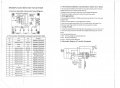
I have just built a function generator kit using the XR2206 I.C, the kit says I can adjust the amplitude of the output via pin 3 from a resistor divider network however I cannot see any adjustment when I use the amplitude potentiometer, the actual variation on pin 3 is from 4.2V to 5.8 volts but nothing happening to my squarewave on the output which remains at 5V pk to pk with a 12V supply....any idea's folks?

Neil.
 

Attachments

Reloadron

Joined Jan 15, 2015
7,517
If we look at the data sheet for the XR2206 monolithic function generator take a look at page 6 the basic test circuit. Take note of where the square wave output is derived, right off the VCO (Voltage Controlled Oscillator) via a 10K pullup from an open collector. You can't adjust the square wave out amplitude as it is a function of VCC. Something is not wired right is my guess as with VCC 12 Volts I would expect about a 12 volt square wave out. That being my guess and only a guess.

There is also this:
"Output DC Level Control The dc level at the output (Pin 2) is approximately the same as the dc bias at Pin 3. In Figure 11, Figure 12 and Figure 13, Pin 3 is biased midway between V+ and ground, to give an output dc level of V+/2".

Ron
 

Thread Starter

Fluxor1964

Joined Jun 11, 2015
182
Thanks Ron...I've been away a while and just set my bench up again....a little rusty here lol

I'm just going to set my square wave to 5V then since I won't use it much just yet, I really need the sine
wave for my transistor amp circuits that I want to experiment with for now.
 

DickCappels

Joined Aug 21, 2008
10,171
From the datasheet:

Output DC Level Control
The dc level at the output (Pin 2) is approximately the
same as the dc bias at Pin 3. In Figure 11, Figure 12 and
Figure 13, Pin 3 is biased midway between V+ and
ground, to give an output dc level of V+/2.
Comment: Apparently, pin 3 is for adjusting offset rather than amplitude.
 

Attachments

Thread Starter

Fluxor1964

Joined Jun 11, 2015
182
From the datasheet:

Output DC Level Control
The dc level at the output (Pin 2) is approximately the
same as the dc bias at Pin 3. In Figure 11, Figure 12 and
Figure 13, Pin 3 is biased midway between V+ and
ground, to give an output dc level of V+/2.
Comment: Apparently, pin 3 is for adjusting offset rather than amplitude.
And of course if I had read the data sheet I would have seen this.....doh!

Thanks people.

Neil.
 
Last edited by a moderator:
Top