XOR gate input spike potentially caused by output

Thread Starter

rubyzzz

Joined May 10, 2023
1
Does anyone have any ideas on why there is a spike on my inputs whenever the output switches on my XOR gate?
This is a XOR gate wihtin the PLL. I have tested multiple PLLs and they all have the same result.

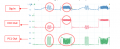
The picture below is the behaviour that I was mentioning, viewed by a picoscope. The green line would be the output causing the inputs (blue and red) to have spikes. Any help would be great. Thanks.

1716546142923.png
 

Attachments

MrChips

Joined Oct 2, 2009
31,195
What you are seeing is most likely an artefact of your measurement system.

Overshoot on sharp transitions are commonly visible as a result of signal reflections on transmission lines.

What oscilloscope and probes are you using?
 

MisterBill2

Joined Jan 23, 2018
19,588
Given that we are not shown "Your Xor Gate circuit", all you can expect is a guess. In that regard, Mr Chips provides a very reasonable guess, based on the waveform displayed.
 

Irving

Joined Jan 30, 2016
4,088
Crosstalk between input and output, esp if the former is high impedance, either in the chip, on the PCB, or even between scope probes, ,is the most likely candidate, The other usual suspect is insufficient or poorly positioned decoupling capacitors on all power rails
 

MisterBill2

Joined Jan 23, 2018
19,588
Really, the very first suspect is oscilloscope probe compensation. Especially as both rising and falling edge spikes are similar amplitudes.
 

MrChips

Joined Oct 2, 2009
31,195
To summarize what is being said, here are possible causes:

1) You are not using proper x10 attenuation probes.
2) The probes are not properly compensated.
3) The probes are not properly grounded.
4) There is cross-talk between probes.
5) The circuit lacks proper decoupling capacitors.
 

MisterBill2

Joined Jan 23, 2018
19,588
OK, if the XOR is in a PLL system it is probably part of a ? "phase frequency detector" circuit and probably CMOS technology. That certainly points a guilty finger at the probe compensation adjustment.
 

WBahn

Joined Mar 31, 2012
30,341
It would sure be nice to have more information -- like a schematic...???

It doesn't look like the problem is the XOR output changing state -- it changes state in a lot of places with no problem.

It looks like something it happening that happens to be causing those particular XOR transitions and you are seeing those spikes as a consequence of those events. So you have more digging to do to identify what other signals are changing then (and, possibly, only then). There's also the possibility that it is nothing more than a measurement artifact. Identifying those can be easier said than done. If it's not a measurement artifact, then there a fair possibility that it is coupling via the power supply or via EMI. You give no indication of your time base, so we don't have any way of even estimating what the frequency content of your edges might be.
 

MisterBill2

Joined Jan 23, 2018
19,588
It is true that some lower priced scopes my not include a compensation adjust signal option.
Usually CMOS circuits do not produce overshoot spikes. Without seeing the circuit it is a bit challenging. And it leads to guessing.
 
Top