Xbox One S Controller Power

Thread Starter

RSGMonkeyMan

Joined Apr 19, 2019
3
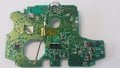
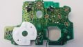
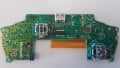
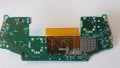
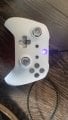
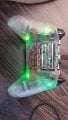
Hello, I am in I'm a little help. I have been a video gamer since I was a child. And now that I am older I wanted to get into customizing Xbox One S controllers, or any other controller for the newer generation consoles and PC. Currently I am trying to hook up 0805 SMD LED in a parallel or series in the controller for Illuminating the buttons and backlight underneath. A lot of videos I have seen on YouTube do not really help. I'm not trying to solder a couple wires to the battery terminal. What I would like to do is wire to the controller so when I push the power button on a controller and it wakes up all the lights will come on at that time. Can anybody help me with this? I am a noob but I am a fast learner. Any help in the matter would be really appreciated. Thank you.
 

Ya’akov

Joined Jan 27, 2019
10,226
Welcome to AAC.

While someone here might already know what the internals of this controller looks like, most of us will have no idea.

If you can take clear, well lit, sharp photos of what you are working on, and include a schematic (or wiring diagram) of what you are trying to do, we can probably help.

Alternatively, if you can link to technical data that provides this information, that can work.
 

Thread Starter

RSGMonkeyMan

Joined Apr 19, 2019
3
This here is the main circuit board for an Xbox One S controller. They're two different parts a top and a bottom. The top piece is where the micro USB power charging connector socket which is located on the underside of the top board. To the left of the micro USB is the two terminals where double a batteries would be inserted. What I want to do is connect to the circuit board where power is first initiated when the controller is turned on. Currently the backlight LEDs are connected to the battery terminal. So I have to take the batteries out to turn the lights off. If I can get it connected to the board to turn on when the controller turns on in the controller turns off that would be much better. Thank you for your help.

Moderators note : removed double uploads
 

Attachments

Last edited by a moderator:

BobaMosfet

Joined Jul 1, 2009
2,211
You may need a Torx security bit to take the controller apart. The name of the game is using as little voltage and current as possible so you don't run the batteries down.
[ed. ignore above, I was typing before you displayed components dissassembled]

I would recommend examining the possibility of using an LED backlight from an LCD display, which can then be lit with a single LED in order to light up behind more than one button at a time. You'll probably have to work with 3.3V and I'd try LEDs at 4mA first, and go up to probably not more than 8mA per LED-- you shouldn't need more than that. I would use an SCR-based circuit to turn all the LEDs on if I pressed 'A' or 'X' for example, and then stay on for 5 seconds before shutting off. Time delay would be controlled by resistor/capacitor timer circuit, and every time a button is pressed the capacitor is filled, essentially restarting the clock. If the controller is left alone, after the timer expires, the LEDs would turn off until next time a button is pressed.
 

Thread Starter

RSGMonkeyMan

Joined Apr 19, 2019
3
BobaMosfet, that would be a great idea, but I'd need more knowledge than what I have at the moment to do that. The ideal thing would be if i could make a pcb with a chip for controlling RGBs, but I'm not that advanced right yet. I would like to know how I could tap into the power so that when I turn the controller on the leds light up then. Right now they leds are connected to the battery terminals, and only work when you turn put the batteries in the controller.
 

BobaMosfet

Joined Jul 1, 2009
2,211
@RSGMonkeyMan- Welcome to electronics. It's mostly and exercise in learning enough about it to then be able to do what you want to be able to do :)

In the short term, the battery provides constant power to the overall circuit. Follow the positive trace on the PCB (from the battery positive terminal) and see where it goes. There's going to be a transistor (likely) acting as a switch that is controlled by a circuit tied to the 'power-on' button. If you can find that transistor, identify it, and then tie your LED circuit into the other transistor lead (not the 'gate' or 'base'), and then when the transistor passes power from emitter to collector or source to drain, it will activate your LEDs.

Be aware, you need to know what your voltage is through that transistor, and then use as little current as you can get away with on the LEDs to start with, to see if it can even power them).
 
Top