Facebook
 Google
 GitHub
 Linkedin
hi C,
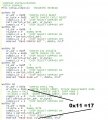
When you have finished the Saving routines, this is a conversion code to Signed Single demo.
The Code between these two
''--------------------------------------------------------------------------
is the actual Code.
E
When you have finished the Saving routines, this is a conversion code to Signed Single demo.
The Code between these two
''--------------------------------------------------------------------------
is the actual Code.
E
Code:
Define CONFIG1L = 0x00
Define CONFIG1H = 0x08
Define CONFIG2L = 0x1e
Define CONFIG2H = 0x00
Define CONFIG3L = 0x00
Define CONFIG3H = 0x83
Define CONFIG4L = 0x80
Define CONFIG4H = 0x00
Define CONFIG5L = 0x0f
Define CONFIG5H = 0xc0
Define CONFIG6L = 0x0f
Define CONFIG6H = 0xe0
Define CONFIG7L = 0x0f
Define CONFIG7H = 0x40
''''Define SIMULATION_WAITMS_VALUE = 1 'Comment in for SIM out for PIC
Define CLOCK_FREQUENCY = 8
AllDigital
TRISA = %00000001
TRISB = %00000000
TRISC = %00000001
PORTA = %00000001
PORTB = %00000000
PORTC = %00000000
PORTE = %00000000
PIR1 = 0
PIR2 = 0
PIE1 = 0
PIE2 = 0
IPR1 = 0
IPR2 = 0
ADCON0 = 0x03
ADCON1 = 0x0e
ADCON2 = %10100100
OSCCON = %01111010 'internal 8mhz
''--------------------------------------------------------------------------
Dim raw_x As Word
Dim Comp_x As Single
Disable High
Disable Low
Hseropen 9600
raw_x = 0x0002 'Test ONLY
main:
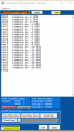
Hserout HexStr(raw_x), " ", ''' Test ONLY
'convert 2s to Single
If raw_x.15 = 1 Then
Comp_x = raw_x Nxor 0xffff
Else
Comp_x = raw_x
Endif
'' Test ONLY
Hserout "Compass x= ", #Comp_x, CrLf
raw_x = raw_x - 1
Goto main
'----------------------------------------------------------------------------------
EndAttachments
-
 21.6 KB Views: 5
 -
 34.6 KB Views: 6
Last edited: