Wrongly READ BITs from peripheral, error? Oshonsoft BASIC

Thread Starter

camerart

Joined Feb 25, 2013
3,724
Hi,
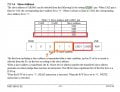
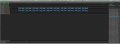
I normally test each 'thing' on it's own, but I just tried removing all of the COMPSS_CS from between each BYTE, and left only the outside ones and 'to my surprise' it still works. (As suggested):)Note: no framing error!
C
 

Attachments

Thread Starter

camerart

Joined Feb 25, 2013
3,724
hi,
The image I posted has a couple of questions in text, please just answer those two questions.:)
Hi E,
1/ It needed zooming in to see the BYTE and the 'what is happening here'
2/ Yes it's DRDY, but today it's DRDY_PIN not as yesterday DRDY_BIT.
C
 

Thread Starter

camerart

Joined Feb 25, 2013
3,724
Hi,
I've been going over the AK8963 D/S in as much detail as I can, and got into a loop.

Here are 4x sections from the D/S, related to multiple READ.

In CAD-VSS it shows to connect CAD0 and 1 to VSS for SPI, which I've done.
In Multiple BYTE READ it starts Muliple BYTE READ with SLAVE ADDRESS, which is shown in CAD 1, where I have VSS making CAD0 and 1 switch to TEST MODE, but I hoped for 0FH which appears to switch OFF I2C.

I'll need to re- read this and maybe edit it, if I've written in incorrectly, as I'm getting a bit mixed up :confused:
Check for EDITs!
C.
 

Attachments

Thread Starter

camerart

Joined Feb 25, 2013
3,724
Cad0-1.jpg is for I2C interface.
SPI does not use slave address.
Hi J,
1/ Can you clarify CAD0-1 please:
When it refers to CS, is this I2C?

2/ In section 7.2.3.2:
Multiple BYTE READ, shows 'slave address' 'register address' 'slave address' If this is I2C, then how is SPI READ in multiple?

Looking through the D/S: Is 7.1 all 4 wire SPI, and 7.2 all I2C?
C
 

Thread Starter

camerart

Joined Feb 25, 2013
3,724
1/ I don't see anything about CS in CAD0-1.jpg, I2C does not use CS

2/ 7.2 is all I2C
Hi J,
1/ It's irrelevant now, but I meant to type 'IC' not CS

2/ How many hours have I stared at I2C? I know more about that than I do SPI, which is what I use :)
3/ In 7.1 SPI, there isn't reference to multi BYTE READ, so is it possible?
C
 

jjw

Joined Dec 24, 2013
823
My guess about multiple read in SPI:
send first address to read from
send dummy byte
data = SSPBUF
send dummy byte
data= SSPBUF
etc.
 

Thread Starter

camerart

Joined Feb 25, 2013
3,724
My guess about multiple read in SPI:
send first address to read from
send dummy byte
data = SSPBUF
send dummy byte
data= SSPBUF
etc.
Hi J,
Seems reasonable!

And I guess, with a CS at the begninning and end of the sequence.

I'll give that a go. I've never tried this sequence before.
C
 

jjw

Joined Dec 24, 2013
823
From 7.1.2
When clocks are input continuously after one byte of data is read, the address is incremented and data in the next address is output. Accordingly, after the falling edge of the 15th clock and CSB pin is “L”, the data in the next address is output on SO pin. When CSB pin is driven “L” to “H”, SO pin is placed in the high-impedance
state.
 

Thread Starter

camerart

Joined Feb 25, 2013
3,724
Hi J and E,
When I read any D/S I have to read and read many times, for me to get any clarity. As you know I appreciate all of your replies, as this makes anything possible (eventually), but the nature of Dyslexia, is that what goes in the eyes, doesn't register in the brain the same way as for you lucky people.
___________________________________________________________________
e,g, E's comment: "Also why are you switching the Comp CS line Hi/Lo for every Clk pulse.? " in #15.

As compss_cs never switches H/L for every CLK pulse, I interpreted this as: 'between every BYTE READ'. I changed compss_cs to 'every batch' of READings.
__________________________________________________________________
As this is all easy to make a mistake, I usually try to post an image, which should look the same as the images in the D/S, (hence drifting into I2C territory for 'multiple BYTE READ'. I don't see multiple BYTE READ for SPI.

So you can see the cycle that makes these threads long. I don't mind, as we usually get through, all these, what are complicated for many of us, I hope you don't mind?

Anyway, thanks, I'll carry on as suggested, and post an image.

Could someone look at the image in #61, which appears to be ok, to me, and comment please?
C
 

Thread Starter

camerart

Joined Feb 25, 2013
3,724
Hi,
On re-checking the image from #61, I notice that there are many repeated numbers, which looks supiciously, like it is READing too fast. So I'll change back to switching compss_cs after READing each BYTE.
C
 
Last edited:

ericgibbs

Joined Jan 29, 2010
18,766
Hi,
Don’t Save each Bit in a Bit array, as your previous Code seemed to show,

Save the Bytes as Hi and Lo Byte in to say, WORD X
Then Hi , Lo into WORD Y
Then Hi, Lo into WORD Z.

When all are Saved into WORD’s X, Y and Z.

Test Bit 15 of WORD X, to check to see if it is a High which indicates a Negative value

If NOT neg then test the next WORD Y Bit 15, and the WORD Z.

IF a WORD has Bit 15 Set High , it is a negative value, so run the 2’s comp conversion routine.
 

Thread Starter

camerart

Joined Feb 25, 2013
3,724
Hi,
Don’t Save each Bit in a Bit array, as your previous Code seemed to show,

Save the Bytes as Hi and Lo Byte in to say, WORD X
Then Hi , Lo into WORD Y
Then Hi, Lo into WORD Z.

When all are Saved into WORD’s X, Y and Z.

Test Bit 15 of WORD X, to check to see if it is a High which indicates a Negative value

If NOT neg then test the next WORD Y Bit 15, and the WORD Z.

IF a WORD has Bit 15 Set High , it is a negative value, so run the 2’s comp conversion routine.
Hi E,
Ok.

This may take a while.
C
 
Top