Wrongly READ BITs from peripheral, error? Oshonsoft BASIC

Thread Starter

camerart

Joined Feb 25, 2013
3,730
hi,
What is the waveform on Channel #4.?
E
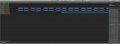
Channel #4 is an asynchronous serial analyser with the SPI analyser above.
It shows any time the PIN goes high, and I've got it in place of a LED, in case it was too fast to see.
I've now connected the LED again, and it's flashing.

Now I've got to use this DRDY BIT inside the READ CODE where it's supposed to be, hopefully.
C
 

ericgibbs

Joined Jan 29, 2010
18,849
hi,
Which Pin on the Compass was the channel # 4 showing.?

What Bit are you referring too.?

You must remember I am not looking over your shoulder while you work on the project, I have to rely on what your posts say, so please be more precise and detailed..:rolleyes:
 

Thread Starter

camerart

Joined Feb 25, 2013
3,730
hi,
Which Pin on the Compass was the channel # 4 showing.?

What Bit are you referring too.?

You must remember I am not looking over your shoulder while you work on the project, I have to rely on what your posts say, so please be more precise and detailed..:rolleyes:
Hi E,
Perhaps you could pop round:)

Yes, words on forums, are not easy to interpret easily. I have great difficulty, but we get there.

Anyway, back to the plot:
I added this CODE just before the COMPASS READ CODE, showing ST1-1, then just after the READ, showing ST-2. All I was after was some movement, as opposed to nothing from the DRDY PIN.
C
Code:
rd_adr = 0x82  'ST1 REG
    rd_Byte = 0  'Dummy BYTE
    compss_cs = 0  'CHIP SELECT COMPASS ON
    data = periph_rd(rd_adr)
    compss_cs = 1  'CHIP SELECT COMPASS OFF
    Hserout "READ ST1-1 =", #data, CrLf
    If data = 0 Then
    yled = 0
        Else
            If data > 0 Then
            yled = 1
        Endif
    Endif
 

ericgibbs

Joined Jan 29, 2010
18,849
hi.
The question is still outstanding.:confused:

Which Pin on the Compass was the channel # 4 showing.?........................................

What Bit are you referring too.? ..............................................
 

Thread Starter

camerart

Joined Feb 25, 2013
3,730
hi.
The question is still outstanding.:confused:

Which Pin on the Compass was the channel # 4 showing.?........................................

What Bit are you referring too.? ..............................................
Hi E,
The SPI analyser section is connected to the compass PINs.

Channel #4 analyser section is connected to one of the LED on the PCB.

Is it possible to check the DRDY BIT, by connecting to the Compass?
C
 

Thread Starter

camerart

Joined Feb 25, 2013
3,730
SSPSTAT.BF is read only Understood.

What is the point of Writing to a Bit Buffer that cannot Read it.???
Hi E,
I don't WRITE to SSPBUF.BF this is used in a WHILE/WEND.

As this was referring to a reply from 'J' #37, perhaps it's a bit confusing to mix the two.

Can someone explain what the SSPBUF.BF should be 0 or 1 please?
C
 

jjw

Joined Dec 24, 2013
823
Hi E,
I don't WRITE to SSPBUF.BF this is used in a WHILE/WEND.

As this was referring to a reply from 'J' #37, perhaps it's a bit confusing to mix the two.

Can someone explain what the SSPBUF.BF should be 0 or 1 please?
C
In #36
'MODE 0,0
SSPSTAT.SMP = 0 'Input data sampled at middle of data output time
SSPSTAT.CKE = 0 '1 Output data changes on clock transition from idle to active
SSPSTAT.5 = 0 'I2C only
SSPSTAT.4 = 0 'I2C only
SSPSTAT.3 = 0 'I2C only
SSPSTAT.2 = 0 'I2C only
SSPSTAT.1 = 0 'I2C only
SSPSTAT.BF = 0 'If SSPBUF=1=Full < -----------
 

Thread Starter

camerart

Joined Feb 25, 2013
3,730
In #36
'MODE 0,0
SSPSTAT.SMP = 0 'Input data sampled at middle of data output time
SSPSTAT.CKE = 0 '1 Output data changes on clock transition from idle to active
SSPSTAT.5 = 0 'I2C only
SSPSTAT.4 = 0 'I2C only
SSPSTAT.3 = 0 'I2C only
SSPSTAT.2 = 0 'I2C only
SSPSTAT.1 = 0 'I2C only
SSPSTAT.BF = 0 'If SSPBUF=1=Full < -----------
Hi J,
I don't understand what your comment means regarding SSPSTAT.BF.
In the program it is set to '0' as you show, should it be removed? or is this correct?
If so then what else should I do?
C.
 

jjw

Joined Dec 24, 2013
823
Hi J,
I don't understand what your comment means regarding SSPSTAT.BF.
In the program it is set to '0' as you show, should it be removed? or is this correct?
If so then what else should I do?
C.
It means that the statement SSPSTAT.BF = 0 is useless, because bit BF is READ ONLY meaning it can only be read, not set to 0 or to 1 by a program instruction.
 

Thread Starter

camerart

Joined Feb 25, 2013
3,730
Hi,
Previously, I posted that I'm not positive that my settings for SINGLE or MULTI READ are correct. Then 'E' asked why I use _CS between each READ ( found this was needed by experiment). I'm pretty sure these two comments are related, and if set correctly, the READs shouldn't need all of the _CS.

Regarding DRDY PIN or BIT! I think to check the BIT, some lines of CODE are needed. I'm not sure how to check this smoothly, while READing, so I'll go back to trying to get the DRDY PIN to work, this would seem much better.
C.
 

Thread Starter

camerart

Joined Feb 25, 2013
3,730
Hi,
I've switched back to DRDY_PIN instead of DRDY_BIT, as I prefer it.
First test with analyser shows 'something'.

Channel 4 shows a serial connection to the DRDY_PIN, and as can be seen it's not lining up with where I think it should be and a 'framing error'.
C
 

Attachments

Top