Wrong Output on Simple Regulated PSU

Thread Starter

sbusso

Joined Mar 6, 2019
11
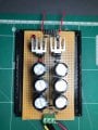
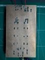
I try to make a simple +/- 12V with a stripboard and an LM7812CV and LM7912. I have a 12-0-12 transformer in input. I m getting 17VDC output on the 2 rails and 10-12V between the 2 rails. I m beginner in electronics and this my first "serious" stripboard project but I cant find where is my mistake, could somebody see what I have done wrong or how to troubleshoot this board ? I have attached pictures of the board and a zip with higher resolution pictures.
 

Attachments

pmd34

Joined Feb 22, 2014
527
Hi sbusso, you may need to place a light load (10mA or so) on the outputs first before you can accurately measure a voltage.
 

Thread Starter

sbusso

Joined Mar 6, 2019
11
thanks, I have added a small load. I still get one rail at 16.5V (left on top view) and 0V on the other one :/.

all the diodes are 1N4004, the positive rail on left (top view) has a 0.33uF capacitor before the LM7812 and a 0.1uF capacitor after. The negative rail has a 2.2Uf before the LM7912 and a 1uF after, based on ST datasheet.
 
Last edited by a moderator:

mvas

Joined Jun 19, 2017
539
Are you 100% sure that you have pin-out correct on the LM7812 & LM7912 ?

In the top side photo, I am guessing ...
the LM7812 is on the left ( Positive Side ) and the LM7912 in on the right ( Negative Side ) ?
Please label your photos.
A schematic would be very helpful.

I cannot see how the Center Pin of LM7812 & LM7912 is grounded?
 

Thread Starter

sbusso

Joined Mar 6, 2019
11
Sorry I didnt have schematic and that is why I gave details of the components. The ground on the LM7912 is on the left pin and directly on a ground line, but not the LM7812, so I will try this right now, thanks !

Are you 100% sure that you have pin-out correct on the LM7812 & LM7912 ?

In the top side photo, I am guessing ...
the LM7812 is on the left ( Positive Side ) and the LM7912 in on the right ( Negative Side ) ?
Please label your photos.
A schematic would be very helpful.

I cannot see how the Center Pin of LM7812 & LM7912 is grounded?
thanks @mvas that was the issue for the positive rail, now I need to find the issue for the negative rail, I guess it is a bad solder, I have fixed one already.

So in the same way, the 7912 input was not pinned with the positive rail. Now I get +12V and -17V I will check ground again.
 
Last edited by a moderator:

mvas

Joined Jun 19, 2017
539
What is the issue with the negative Rail ?

Top side photo.. the LM7912 in on the Right side / Negative Side ?
Ground side of LM7912 looks OK
How are you getting RAW (-) Rail Power the Center "Input" Pin of LM7912 , through a diode ?

Were are your Heat Sinks ?
 

Thread Starter

sbusso

Joined Mar 6, 2019
11
@mvas, the raw(-) was missing. I have linked it and now I have -17V so I may have another pin issue.

Those heat sinks dont have pins.

the fact is I setup everything first and moved the LMs to give more space to the heat sink and in the mean time tried to save connection. By doing so I have messed with the pins
 
Last edited by a moderator:

djsfantasi

Joined Apr 11, 2010
9,160
@mvas, the raw(-) was missing. I have linked it and now I have -17V so I may have another pin issue.

Those heat sinks dont have pins.
The tab to which the heat sinks are connected, is the same as the center pin on both devices. On the 7812, the tab connects to ground. On the 7912, the tab connects to the input voltage.
 

mvas

Joined Jun 19, 2017
539
So, your heat sinks are "floating" - no connection to any copper pad or each other? = OK.
It is so hard see the actual problem around the LM7912.
 

djsfantasi

Joined Apr 11, 2010
9,160
So, your heat sinks are "floating" - no connection to any copper pad or each other? = OK.
It is so hard see the actual problem around the LM7912.
But they are connected! The 7812 is connected to ground. The 7912 is connected to its input voltage
 

djsfantasi

Joined Apr 11, 2010
9,160
Are you 100% sure that you have pin-out correct on the LM7812 & LM7912 ?

In the top side photo, I am guessing ...
the LM7812 is on the left ( Positive Side ) and the LM7912 in on the right ( Negative Side ) ?
Please label your photos.
A schematic would be very helpful.

I cannot see how the Center Pin of LM7812 & LM7912 is grounded?
The center pin of the 7912 shouldn’t be connected to ground. It should be connected to the input voltage.

Read the datasheets before posting.
 

djsfantasi

Joined Apr 11, 2010
9,160
Yes, I know.
It appears the Heat Sinks are "floating " because they connected to the IC's ony.
I am waiting for TS to verify.
Did you read the datasheets I linked to?

The heat sinks in his image do not appear to be insulated. Which means that there is conductivity between them and the tab.

Since the tab is connected internally to the center pin of the regulators, the heat sink is connected to the center pin. Since the center pin of the 7812 is connected to ground, the heat sink is also connected to ground. Not floating.

A similar description can be had regarding the 7912’s heat sink and it’s input voltage. Again, not floating.

Sorry, but I can’t understand why you think the heat sinks are floating...
 

mvas

Joined Jun 19, 2017
539
The center pin of the 7912 shouldn’t be connected to ground. It should be connected to the input voltage.

Read the datasheets before posting.
My message #4 is 8 hours old, prior to bugs being found and fixed.
See my message #6 ... Connection of RAW (-) Power to 7912 Input is fixed !
You are very late to this party...
 

mvas

Joined Jun 19, 2017
539
Did you read the datasheets I linked to?

The heat sinks in his image do not appear to be insulated. Which means that there is conductivity between them and the tab.

Since the tab is connected internally to the center pin of the regulators, the heat sink is connected to the center pin. Since the center pin of the 7812 is connected to ground, the heat sink is also connected to ground. Not floating.

A similar description can be had regarding the 7912’s heat sink and it’s input voltage. Again, not floating.

Sorry, but I can’t understand why you think the heat sinks are floating...
Floating ... as in not connected anything but the IC.
 

djsfantasi

Joined Apr 11, 2010
9,160
Floating ... as in not connected anything but the IC.
Can you clarify a couple of terms for me? What is your definition of floating? And why is the fact that the heat sinks are “floating” is of concern to you?

Your usage of “floating” is nothing that I see as or can find as an electronics term.

You have defined it as “because they connected to the IC’s ony”. I thought I had clearly demonstrated that this is not true. Each heat sink IS connected to the circuit.

You also refer to floating as:
So, your heat sinks are "floating" - no connection to any copper pad or each other? = OK.
Also not true. The heat sinks are both connected to a copper pad. Could you re-read post #14?

As far as my second question, I don’t understand why you are concerned about “floating heat sinks”? IMHO, heat sinks should NOT be connected to anything. In the TS circuit, one heat sink is connected to ground and the other to the voltage input. If something metal, like a case, were to bridge the two devices, we’d have a short.

When I use heat sinks, I insulate them with a plastic bushing and an insulating pad. This prevents short circuits.
 

Thread Starter

sbusso

Joined Mar 6, 2019
11
So I got it working ! The last errors were the diiode around the 7912 that was in the wrong direction. I first removed it and put it back as it was not solving the issue, and then I have redone solders of the 7912, and it was still not working, then removed again the diode to finally get around -12V.

That was a good experience and big mess for small circuit. Good lessons learned and big thanks to @mvas and @djsfantasi, it would have taken few more evenings to figure those out without your help, the discussion on the heat sink was also very informative. Theory is one thing but for electronic practising is much more educating :)
 

atferrari

Joined Jan 6, 2004
4,768
So I got it working ! The last errors were the diiode around the 7912 that was in the wrong direction. I first removed it and put it back as it was not solving the issue, and then I have redone solders of the 7912, and it was still not working, then removed again the diode to finally get around -12V.

That was a good experience and big mess for small circuit. Good lessons learned and big thanks to @mvas and @djsfantasi, it would have taken few more evenings to figure those out without your help, the discussion on the heat sink was also very informative. Theory is one thing but for electronic practising is much more educating :)
When I started to learn electronics, and precisely with this very subject (and also 555 based designs) I found myself many times saying "it should work".

Since I was just learning with no pressure to have it running "right now" and having seen that I was in circles around a non solution, the best was always, to throw away everything (disassemble, bah) and start afresh. Worked, dare to say, 100% of the times. I think the reason is that who checks what mistakes happened is the same guy that did them, that is YOU.

By now, I heard professionals here, saying how wrong I was. I am conscious that the capability to debug an own circuit, you develop it with time. I did to a certain extent and stopped starting everything again as suggested above.

In my work, at the time I was a Chief Officer in vessels, the trim / stability calculations were run by hand with just a calculator. I developed strong and precise habits to advance after verifying previous steps. Pretty much the same with astronomical calculations (pre-satellite times). It saves debug time.

It worked for me, as now, when I wire anything on a PCB or a protoboard.

But, hey, that is me.
 
Top