 Facebook
 Google
 GitHub
 Linkedin
Hi! I'm not sure if this is the correct subforum to ask this question in.
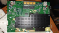
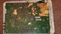
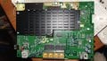
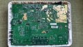
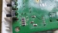
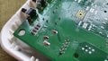
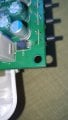
I am trying to repair a V1 TP-Link Archer VR900 router which I just picked up second hand. The power electronics seem to have failed as both chargers I've tested will make a ticking noise which is likely some sort of protection function and the device won't start. Upon disassembly it looks like at least 2 capacitors have come off the board - C3 & C5 the former of which I saw was half-attached and came off with a light touch from my screwdriver.
Not sure how this damage would occur, but I want to attempt a repair even though the router was of little expense. I like to fix things!
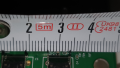
From a bit of research, I believe the capacitors are ceramic capacitors? They are 1mm in length. The device is rated at 12V dc up to 3.3 AMPs, and the capacitors are positioned on the other side where the dc jack power socket is, I suspect it's part of the power electronics.
C3 looked the same as C321 - but I have no idea what sort of specs these capacitors have as they're too small to have any identifiable details printed on them, can somebody help and advise what may be a suitable replacement - preferably one which would be easier to solder than these tiny 1mm cuboid capacitor. If they can't be identified what would be your best guess at a replacement capacitor which may work in this circuit?
Here's some photos:
Many thanks!
I am trying to repair a V1 TP-Link Archer VR900 router which I just picked up second hand. The power electronics seem to have failed as both chargers I've tested will make a ticking noise which is likely some sort of protection function and the device won't start. Upon disassembly it looks like at least 2 capacitors have come off the board - C3 & C5 the former of which I saw was half-attached and came off with a light touch from my screwdriver.
Not sure how this damage would occur, but I want to attempt a repair even though the router was of little expense. I like to fix things!
From a bit of research, I believe the capacitors are ceramic capacitors? They are 1mm in length. The device is rated at 12V dc up to 3.3 AMPs, and the capacitors are positioned on the other side where the dc jack power socket is, I suspect it's part of the power electronics.
C3 looked the same as C321 - but I have no idea what sort of specs these capacitors have as they're too small to have any identifiable details printed on them, can somebody help and advise what may be a suitable replacement - preferably one which would be easier to solder than these tiny 1mm cuboid capacitor. If they can't be identified what would be your best guess at a replacement capacitor which may work in this circuit?
Here's some photos:
Many thanks!


")


