Facebook
 Google
 GitHub
 Linkedin
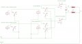
In your drawing for the suggested position for the down microswitch apart from the fact you have a link shorting it out it will not work as there will still be current flowing through the C1 to D1 winding on the motor via the capacitor. You would need to keep the blue wire (B2) connected to the capacitor (Black wire C2.) and insert the microswitch between that point and the top right hand connection on the rocker switch. If you are retaining the existing remote handset you would need an extra core on the cable or move the capacitor to near the motor. Is it your intention to retain the existing remote or will it be reptaced with two wireless remotes ? I have two of the 4 channel wireless remotes the same is the ones that Ron suggested. They work very well. I don't know anything about the other units that are powered from 110 volts AC (Rather than 12 volts DC.) From the advert for them they should work. Although the ratings on the relays in these remotes should be enough for the motor current I would not trust them. I would use them to drive two larger relays / contactors. When you say exactly the way you want it to work I will suggest a schematic. I had another thought as an alternative to a gearbox and cam to operate the down microswitch. It would use a length of threaded rod driven from the winch drum shaft. A nut on the shaft could operate the microswitch as it moved along the rod. (About how many revolutions will the drum make for the full travel from the lowest position to the highest position ?)
Les.
Les.
Les.
Les.

 I don't see the need for a wireless remote, since to carry out loading and unloading of the platform safely someone would have to be next to it and could easily operate a hard-wired switch.