hi,
As I said in my first reply post you cannot use a bss138 in that Source load circuit.
Do you have any P MOSFETs or NPN transistors on the bench.?
E
hi,
As I said in my first reply post you cannot use a bss138 in that Source load circuit.
Do you have any P MOSFETs or NPN transistors on the bench.?
E
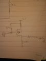
About 10 kohms? in order to simplify the circuit, ive attached a circuit.
Im giving input to the source with gate pulled upto 3.3 volts. The drain is connected to the motor driver. When my input is 3.3 volts, Vgs = 0 and the mosfet is off, hence the drain voltage is 5 volts. When my input is 0 volts, Vgs=3.3 volts and mosfet is on and the drain is at 0 volts ( same as input).
I haven't read the full datasheet in detail, but it looks like it has enable pins which would do exactly what you want without any additional components. Maybe I'm misreading it, but here's what I was looking at:
When the gate is floating or the gate is 3.3V then the Vs will be connected to Gnd and when the Vgs is 0V then the Vs will be as output 5V, but this is not a good way to output a low level to control the P MOSFET in this case, especially when the uC initialing that the output is a low level and it could be causes the Vs goes high.
I thought earlier the driver was getting 5V supply. Also, the microcontroller was 3.3V logic, right? If so, your circuit is a bad idea, because you'll be exposing the microcontroller to 5V on its GPIO pin when it's off.
Again, why not just use the enable pins on the driver? No extra components needed (unless I'm misreading the datasheet.)
*** EDIT: I see now that the quiescent current of the driver is relatively high. I can understand why you wouldn't want to rely on enable pins alone if this were a battery powered device and power management was important.
If you need a level shifter, just use use a simple BJT. They usually have lower capacities than fets and are cheaper. Additionally, you don't have to worry about not completely turning them on with only 3.3V. Why use a mosfet here?
If you need a level shifter, just use use a simple BJT. They usually have lower capacities than fets and are cheaper. Additionally, you don't have to worry about not completely turning them on with only 3.3V. Why use a mosfet here?
A MOSFET can easily have a much lower voltage drop (a function of Rds-on and current) than a BJT's CE voltage drop, so there's at least one reason.
As for turning it on, the last circuit proposal uses a P-MOSFET and a pull-up resistor, then uses an active low signal from the microcontroller to turn on the MOSFET. As such, there will be 5V across gate and source when MOSFET needs to conduct, not 3.3V.
60 mA on the input or output? If that was an issue, you could use a higher gain BJT or a darlington transistor setup. But then I guess you may as well use a mosfet, unless speed was really an issue.
60 mA on the input or output? If that was an issue, you could use a higher gain BJT or a darlington transistor setup. But then I guess you may as well use a mosfet, unless speed was really an issue.
 Facebook
 Google
 GitHub
 Linkedin