Will a 555 timer switch on and off, on and off, etc?

Thread Starter

pityocamptes

Joined Jul 25, 2012
84
I have a small air pump that needs to cycle, the pump draws very little current and voltage ~3.5 volts. Its a mini pump. The specs say 7 seconds on and 7 seconds off for duty cycle. Will a 555 timer circuit do this? 7 secs on and 7 off, 7 on and 7 off, etc until the unit is powered off via a control switch? Anyone have a schematic that I can reference? Thanks!
 

tracecom

Joined Apr 16, 2010
3,944
I have a small air pump that needs to cycle, the pump draws very little current and voltage ~3.5 volts. Its a mini pump. The specs say 7 seconds on and 7 seconds off for duty cycle. Will a 555 timer circuit do this? 7 secs on and 7 off, 7 on and 7 off, etc until the unit is powered off via a control switch? Anyone have a schematic that I can reference? Thanks!
Yes, a 555 in the astable mode can supply the timing to control the pump. The 3.5 V is not a problem for the 555, but the missing data is the current the pump draws. Probably the 555 won't be able to handle the current and will require a driver. I assume the pump is DC powered; is that correct? And how much current does it draw...both running and during startup?
 

Thread Starter

pityocamptes

Joined Jul 25, 2012
84
Yes, a 555 in the astable mode can supply the timing to control the pump. The 3.5 V is not a problem for the 555, but the missing data is the current the pump draws. Probably the 555 won't be able to handle the current and will require a driver. I assume the pump is DC powered; is that correct? And how much current does it draw...both running and during startup?

Yes, the pump runs at 3 - 3.2 V (dc) with less than < 150ma. I was hoping to power the pump and timer off the same power supply of 3 volts. Will this work, or will I need two seperate supplys with a small reed style relay triggered by the 555 to run the pump? Also, I see that they make a low voltage icm7555 chip - should I look at that one for the small voltages I am working with? Thanks! Restart voltage on the pump is 2 volts dc.
 

wayneh

Joined Sep 9, 2010
18,164
That IC has a max output current of 100mA, so NO. But a single transistor used as "relay" or switch would let you use any timer IC you want. Timer output to base, emitter to ground, collector to low voltage side of pump.

Oh, and you need the "astable multivibrator" circuit for the 555.
 

Thread Starter

pityocamptes

Joined Jul 25, 2012
84
That IC has a max output current of 100mA, so NO. But a single transistor used as "relay" or switch would let you use any timer IC you want. Timer output to base, emitter to ground, collector to low voltage side of pump.

Oh, and you need the "astable multivibrator" circuit for the 555.

Can you post a simple schematic of the use of a transistor as a switch? I'm more visual. Thanks!
 

wayneh

Joined Sep 9, 2010
18,164
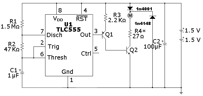
Take a look here. Picture your motor as the LED, or in parallel with it. That circuit uses two transistors in a darlington pair, which is nice, but you could get by with a single one.
 

Thread Starter

pityocamptes

Joined Jul 25, 2012
84
Thanks! Would I need a flyback diode on that circuit for the pump? If so, where exactly and which diode?

Also what does R3 do in that circuit?
 
Last edited:

wayneh

Joined Sep 9, 2010
18,164
Thanks! Would I need a flyback diode on that circuit for the pump? If so, where exactly and which diode?

Also what does R3 do in that circuit?
The flyback diode won't hurt and is probably a good idea, but you can eliminate that diode in series with the motor.

R3 limits the base current on that transistor. The base current on the other is limited by the output of the 555, which can tolerate a short there, I believe. Or at least it can tolerate the base current, which is about 10% of that required to drive the pump.
 

Thread Starter

pityocamptes

Joined Jul 25, 2012
84
So eliminate the 1n4001? Not sure I follow the rest of your response. Sorry about that, been a while since I have been in electronics. So are you saying that that circuit will NOT or will drive the pump? Thanks again. If NOT, what must I do or change to get it to drive the pump?
 

wayneh

Joined Sep 9, 2010
18,164
Yes, drop the 1N4001.

I'm not sure about R4. Isn't your motor fine running at 3V, in other words you could connect it directly to your batteries? If that's true, you don't need R4.

Otherwise, I think it'll all work fine. I'd experiment with eliminating Q1 and R3 also, using just the 555 output connected directly to the base of Q2. The only purpose of Q1 is to provide more base current to Q2. If you can turn Q2 fully on without it, that's fine.

Oh, and I didn't look at the timing components, R1, C1 and R2. Make sure they suit your needs.
 

Wendy

Joined Mar 24, 2008
23,816
Always interesting to see one of my drawing modified, don't mind a bit! Eliminate R4, the motor is the load. You said your motor needs 3.0 - 3.2V? Eliminate the 1N4001, it is not needed. Use a Shottky Diode instead of the 1N4148, it could be important.
 

Thread Starter

pityocamptes

Joined Jul 25, 2012
84
Yes, drop the 1N4001.

I'm not sure about R4. Isn't your motor fine running at 3V, in other words you could connect it directly to your batteries? If that's true, you don't need R4.

Otherwise, I think it'll all work fine. I'd experiment with eliminating Q1 and R3 also, using just the 555 output connected directly to the base of Q2. The only purpose of Q1 is to provide more base current to Q2. If you can turn Q2 fully on without it, that's fine.

Oh, and I didn't look at the timing components, R1, C1 and R2. Make sure they suit your needs.

Yes, motor is running at 3-3.2 volts at <150ma, restart voltage 2.0 volts
 

Wendy

Joined Mar 24, 2008
23,816
If you are using a CMOS 555 as shown you will need both transistors, there is a very good reason I did that. Basically CMOS does not have very good drive characteristics.
 

Thread Starter

pityocamptes

Joined Jul 25, 2012
84
If you are using a CMOS 555 as shown you will need both transistors, there is a very good reason I did that. Basically CMOS does not have very good drive characteristics.

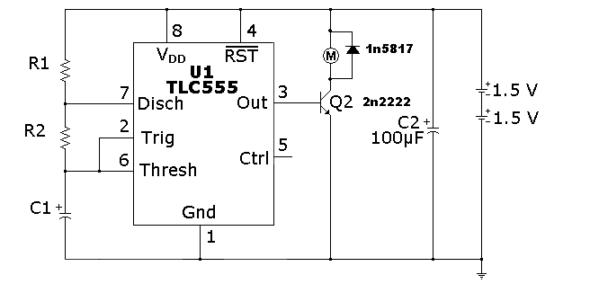
Yes, I will have to as my power restrictions are low. Thanks, I will include that back into the schematic. Besides adding that back in, all looks good? I may drop a .01 uf cap on pin 5 to offset any noise. Thanks.
 

wayneh

Joined Sep 9, 2010
18,164
If you are using a CMOS 555 as shown you will need both transistors, there is a very good reason I did that.
I suspected as much but wasn't sure. Your experience saves the OP running the experiment I suggested earlier. Just use the second transistor and move on.
 
Top