The frequency compensation capacitor in an opamp is usually 30pF and connects from collector to base on the common-emitter amplifier transistor that has the most voltage gain.
The frequency compensation capacitor in an opamp is usually 30pF and connects from collector to base on the common-emitter amplifier transistor that has the most voltage gain.
Uhm... that makes sense, but isn't a pJFET designed not to operate with positive Vds voltages?
Anyway, I've tried your suggestion and it works if I add a discharge resistor in parallel with the capacitor on the JFET's gate. But there's still the problem with negative swing, it doesn't go as much as the positive one and there are spikes on the negative side when I increase the gain.
As you can see in the plots I posted, the FET is symmetrical. Source and drain are interchangeable, and this is why they will work as a voltage-controlled resistor. Besides, what does Vds have to do with the issue at hand, which is Vgs?
Your slew rate limitation is obviously what is giving you the triangle wave output. Try making the bridge caps 10 times bigger, to lower the oscillation frequency (and the required slew rate). You also need to run the sim for 100's of milliseconds to let the peak detector settle out.
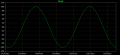
I've been playing with the problem on LTspice, and I have a nice circuit that puts out 20V p-p into 600 ohms, with +/-12V supplies. It has distortion on the order of -60dB (remember, this is a sim).
What do you think, forum members? Should I post it? Since this is a homework problem, I'm reluctant to just give it away, although one person did post a link, but the circuit wouldn't drive 600 ohms.
Speaking of that, If you want to build an oscillator that will drive a low-impedance load, it would make sense to put a buffer amp between the oscillator and the load.
When the oscillation frequency is lower the circuit behaves better but I need it to run between 3KHz and 18KHz. Anyway, today I have to make the presentation for this, we'll see what the teacher says. Thank you for you feedback (yeah, pun)
What do you think, forum members? Should I post it? Since this is a homework problem, I'm reluctant to just give it away, although one person did post a link, but the circuit wouldn't drive 600 ohms.
Well, your advice sure payed up in the end, I got an A
My teacher said that he didn't want a 'perfect' solution, he gave us this exercise just for us to see what analog design is really like and to help our understanding of these principles by really doin' it.
Thank you again for your advice!
Yeah, congratulations to Hash! He deserves accolades for understanding a very complex circuit, and getting that "A".
As for me... Put my money where my mouth is, huh? Ok, ya got me.
Just kidding.
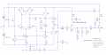
I originally wrote a book here, but decided it was a little over the top. Below are the schematic and waves. If anyone has comments or questions, shoot!
The circuit that I've presented was the last one I posted here.
@Ron: Your advice was of great use for me, don't get me wrong, I also appreciate you not just 'giving it away' for me, and wow, this looks... nice
Don't know where to start analysing it from, I see the LTP, feedback networks but everything in between is kinda blurry, would you mind explaining in detail how and why it works, I'm interested to know how did you think of it, why did you put those exact values there. I know experience is of great use but are there some tips regarding the design of the various amplifier stages? Also I would like to know what do all those capacitors do in the negative feedback loop.
Thanks again, and I would mention that I like reading books
You read that wrong. Considering it was a homework assignment, and everyone realizes how hard people work to help and want to post their own results, it's a difficult choice on posting before the OP gets their grade.
You read that wrong. Considering it was a homework assignment, and everyone realizes how hard people work to help and want to post their own results, it's a difficult choice on posting before the OP gets their grade.
Joe, I'm not sure what you thought I read wrong. As I said, I was "just kidding".
Hash, below is what I originally was going to say in my post where I put up the design. Read that over and come back if you have more questions.
I had fun playing with this. The hardest part was the amplitude stability compensation network on the gate of the JFET. A simple peak detector has problems with squegging, or at least damped oscillation.
The discrete op amp is obviously a wasted effort, except as an exercise. An IC would be better. This one has 90+dB open loop gain, and the unity gain frequency is something like 3MHZ (can't remember either number exactly). Slew rate is unremarkable at about 3.5V/usec.
I thought the common-base peak detector (Q12) was a nice touch. Obviously, you could use an NJFET and an NPN peak detector, which would actually be my choice. I used a PFET because that's what Hash was using.
I gotta admit this came out better than anticipated. I was astounded at the lack of harmonic distortion. Even what you see on the FFT plot may due be in part to sim sampling rate. Before I set it at 100ns max, 3rd harmonic distortion was like -50dB relative to the fundamental. The sim time gets really long when you set max sample time to be short. The FFT was actually taken over a sweep time that started at 200ms and ended at 300ms, relative to time=zero.
 Facebook
 Google
 GitHub
 Linkedin

")