Wien-bridge oscillator

Thread Starter

Amir Sarikhan

Joined May 29, 2015
45
Hi all
I designed a wien-bridge oscillator
I attached the schematic
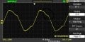
When I increase the frequency about larger than 10khz the resulting sinusoid get some problems that I specified on picture . Why these are happening ?
And when the frequency is below 10khz the shape is smooth but is little different than sinusoid .
Can I get better shape than this ? and why is it little different than sinusoid ?
 

Attachments

MikeML

Joined Oct 2, 2009
5,444
Also, a "real" Wein Bridge oscillator needs to have an automatic gain control to actively keep the amplifier gain of 3.001. Yours has no gain control, so as the oscillations build up, the opamp runs into its Output voltage limits, causing severe distortion.

To make a 10kHz oscillator, the GainBandwidth Product of the opamp should be greater than 1MHz.

Your gain setting resistors are much too low in resistance. Try 22K and 10K or 220K and 100K. The closed loop gain is set to 1+22/10 = 3.2, so the amp has too much gain for clean sine waves. Try setting the gain much closer to 3.
 
Last edited:
Hi,
MikeML's answer is far to technically advanced for I to complete it on this way, but maybe you're wondering why an op amp could not follow the signal when the frequency gets too high, and this is a question of physics actually (of course, like everything in our world :))
An op amp is made of many transistors, which use a physical technology comparable to diode's : a chemical mechanism to have a non-linear behaviour (when looking the i = f(v) curve) which, because of it's chemical nature, is quite slow ...
 

crutschow

Joined Mar 14, 2008
34,426
MikeML's answer is far to technically advanced for I to complete it on this way, but maybe you're wondering why an op amp could not follow the signal when the frequency gets too high, and this is a question of physics actually (of course, like everything in our world :))
An op amp is made of many transistors, which use a physical technology comparable to diode's : a chemical mechanism to have a non-linear behaviour (when looking the i = f(v) curve) which, because of it's chemical nature, is quite slow ...
You're way off. There's nothing chemical about diode or transistor operation. It's called sold-state physics for a reason.
The speed of diodes and transistors is mostly determined by the transit velocity of the carriers in the semiconductor material.
The non-linear nature is due to the characteristics of how these carriers cross a PN junction.
No chemical reaction anywhere in their operation.
Indeed, no chemical reaction, sorry if I wasn't understandable.
I know that physicians ans chemists don't like each other verry much :D but I've learned it in a crystallochemistry course and in electronics, they often say it too so I think we can say that it's chemistry, even if there is no reaction ...
Anyway, electrons don't move in the conduction band, contrary to what happens in a metal crystal, and (it may be wrong, but I don't think so) that's why it's a slow process, unlike self or capacitor
 

ian field

Joined Oct 27, 2012
6,536
I set resistors for get the gain near 3
The usual method of controlling gain is a negative feedback path shunted by a filament bulb, the filament has a PTC so if the feedback increases, the filament gets higher resistance and lets more of it through. Some recent designs use a JFET, but they cause distortion.

The last one I saw the schematic for, used a 28V 24mA wedge-base telephone switch board bulb.

If you can ever get hold of one - the PTC thermistor RA52 is often specified for professional oscillators.
 

crutschow

Joined Mar 14, 2008
34,426
Below is the simulation of a Wein oscillator slightly modified from the Examples directory in LTspice.
It uses negative feedback from the output to the JFET gate to regulate the output amplitude. The JFET acts as a variable resistor to control the closed-loop gain. The AC drain-source voltage is about ±30mVpk to minimize non-linear effects and distortion.
Note that the simulation works fine at 10kHz with an LM324 model.

Wein Osc.gif
 
Last edited:

AnalogKid

Joined Aug 1, 2013
11,040
The speed of diodes and transistors is mostly determined by the transit velocity of the carriers in the semiconductor material. .
And, junction capacitance.

Every bipolar transistor has two PN junctions, and there are three parasitic capacitors among the junctions. The capacitance between the base and the collector acts as a form of negative feedback to form an itegrator, or lowpass filter. This can improve the stability of the opamp, but it also limits its open circuit bandwidth, which affects how well it can handle high frequency signals.

ak
 
Top