Wien Bridge Oscillator simulation not working in LTSpice

Thread Starter

Nobby Nobbs

Joined Jul 31, 2014
11
Hi all, I am having trouble getting this simulation to work. I am a complete novice at LTSpice but the question seemed simple enough, simulate Wien bridge in LTSpice and printout the transient response.
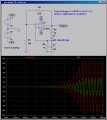
I can do that I thought but it seems not. I have simulated the circuit but the output does not oscillate it just sits at 11V see below, top is the circuit from the course work, then my circuit and output.


I have tried a couple of other wien bridge circuits of the web, some shown in LTSpice and shown with an output chart but when I copy them I just get a flat line output.
Can any one give me a pointer as to what I am missing how do you make an oscillator oscillate?

Thanks for any advice you can offer.
 

MikeML

Joined Oct 2, 2009
5,444
Post your .asc file so I don't have to recreate it from scratch...

Note that the output rails at +11V. Think about where the inputs are connected. What is the DC gain of the circuit? Is the feedback correct to bias the output of the opamp to near zero V?
 

Thread Starter

Nobby Nobbs

Joined Jul 31, 2014
11
Thanks for the reply, I have attached the file as requested.

Re your other points, I am currently reading up on the biasing for opamps to see if I could figure anything out but have only just started to learn about them. This section of the course is about computer simulation and getting the outputs from LTSpice. So really you just copy the circuit to see the output, then it asks you to change a couple of components and compare the results but as far as I was aware this circuit should work I am not expected to alter anything.

but as I said I have copied another circuit I found on Google that was built in LTSpice and showed the circuit and output but if I ran it I just got a flat line.

Thanks again for the reply.
 

Attachments

Thread Starter

Nobby Nobbs

Joined Jul 31, 2014
11
I know the formula for the gain of a Non inverting and an Inverting opamp gain.
G=1+R1/R2 for Non inverting and G=R1/R2 for an inverting opamp but this circuit seems to have resistors in both positions so I am somewhat confused to say the least. :confused:

Forgive my ignorance we have not covered the Wien bridge oscillator at all in the course work so to be honest I haven't a clue how they work, I am reading on various web sites about them now.
 

MikeML

Joined Oct 2, 2009
5,444
Stare at what I did to your circuit...

Come back and let me know you understand what it took to fix it...

Why does it take some time for the oscillations to build up?

What limits the final amplitude?

Why is the output more-or-less centered on zero V?

What is the Barkhausen Criterion?

btw- This was not an LTSpice problem. The simulation predicted exactly what would happen to the circuit as you had it wired initially...
 

Attachments

Thread Starter

Nobby Nobbs

Joined Jul 31, 2014
11
Good grief how simple was that the internal + and - is the wrong way round on the diagram from the course work so I copied it.

You flipped the amp over so the inverting input is at the top and Boom it works.

That is a whole day I have spent swearing at this computer. That will teach me to trust the course work, getting a bit fed up with the mistakes in this. Although I should have spotted that as I have been looking at circuits all day :(

I will now go off and try to find the answers to your other questions, but not today I need to get away from this pc and go out for a run.

Thank you for your help
 

crutschow

Joined Mar 14, 2008
34,285
Any Spice program can occasionally give erroneous results due to time-step or convergence problems, but generally when the Spice results appear incorrect, it's because of a problem in the circuit.
 
Top