Wien Bridge oscillator not forming clear sinusoidal wave

Thread Starter

jxrxmyrxss

Joined Oct 24, 2020
1
1603687206235.png
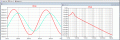
This is my running circuit and its waveform. I have met the requirements set by my instructor in which Vrms=2.5 and is operating at <100Hz. My only problem is now making a sinusoidal waveform. I have tried a bunch of things like removing the C2 capacitor and adjusting some of the values but still have failed to obtain a clear sinusoidal wave. Need some tips how to achieve it. Thank you very much!
 

LvW

Joined Jun 13, 2013
1,752
At first, remove C2.
You need dc negative feedback for proper operation of the opamp.
Secondly, the amplifier must provide a fixed gain of "3", which means that the ratio R1/R2 must be"2".
However, for a safe start of oscillation this ratio must be slightly larger than "2" (2.05...2.1).
Even in this case, there will be no clean sine wave because the amplitudes will be "clipped" .
To improve the circuit you can use one of the known methods for "soft" limiting (automatic amplitude control)
 

MisterBill2

Joined Jan 23, 2018
18,167
The opamp is being driven into non-linear operation in both directions. First, the supply voltage is too low, both positive and negative. Thus you may also need less gain. The amplifier is getting more feedback than it should have.
 

MisterBill2

Joined Jan 23, 2018
18,167
If you look at the supply voltage it is clear that it has been adjusted to set the output amplitude. And then look at the wave form and it is clear that the amplifier is being driven beyond what it can handle in a linear manner. The student should go back and review the material about amplifiers and their limitations, and then look at some of the classic Wein bridge oscillator circuits.
If an addition to the circuit is allowed then a resistor in series with the amplifier output can be added.
 

Audioguru again

Joined Oct 21, 2019
6,672
2.5V RMS is 7.07V peak-to peak. The waveform shows only 2.4V + 3V= 5.4V p-p which is why there is severe clipping.

I agree that the supply voltages are too low and the gain should be adjusted for a little more than 3 to start then reduced to exactly 3 to oscillate cleanly.
 
Last edited:

MisterBill2

Joined Jan 23, 2018
18,167
Good point about the RMS part. Some sneaky instructor there, adding a snare for those who are not extra careful. Mostly though, folks read peak to peak on a scope, as well as on a simulated scope. I did not look up the specs on that particular device, LT1013, it might even be a low voltage device to really trick the students.
 

Ian0

Joined Aug 7, 2020
9,667
Most of these circuits predate rail-to-rail op-amps. If the gain is set to 3 and a little bit, then the clipping which is provided by the diodes to reduce the gain to 3, will be provided Instead by the output stage clipping. Distortion is about the same as the diode clipper, but uses fewer components and has a very predictable output voltage which isn‘t dependent on a fairly random and Temperature-dependent diode forward-voltage drop.
If you need better distortion than that, you will have to use one of the JFET circuits.
 

Ian0

Joined Aug 7, 2020
9,667
The Linsley-Hood circuit from 1981 is a particular favourite.
One method that worked far better than I ever thought it would uses two inverters from a 4069UB or 74HCU04.
R2=2.R1+ε
where ε is that extra little bit that it needs to start it oscillating.
it stabilises because the gain of the inverter reduces as its output voltage gets close to the supply rail.

But if you prefer the original method of amplitude stabilisation, where a you going to get a filament lamp these days?!
 

Attachments

Last edited:

MisterBill2

Joined Jan 23, 2018
18,167
The Linsley-Hood circuit from 1981 is a particular favourite.
One method that worked far better than I ever thought it would uses two inverters from a 4069UB or 74HCU04.
R2=2.R1+ε
where ε is that extra little bit that it needs to start it oscillating.
it stabilises because the gain of the inverter reduces as its output voltage gets close to the supply rail.

But if you prefer the original method of amplitude stabilisation, where a you going to get a filament lamp these days?!
There are lots of filament lamps available, but they are the very small ones. Not found at those venues that carry only the very most popular items, though.
 

Ian0

Joined Aug 7, 2020
9,667
hi,
The Bubba sine wave osc gives a good quality sine wave output.
E
The image inset is the Fourier plot
And it gives both sine and cosine.
Who was Bubba, and how did he get his name on what I thought was just another phase-shift oscillator?
 

Audioguru again

Joined Oct 21, 2019
6,672
I use a stepped digital "sinewave" followed by an 8th-order Butterworth lowpass switched capacitor filter IC. The output level is rock solid with extremely low distortion and the oscillator for the digital sinewave counter is the same oscillator for the switched capacitor filter.
 
Top