Wide Range Input (Sinking/Sourcing) to Arduino

Thread Starter

jonfarrugia

Joined Feb 19, 2010
71
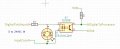
So I've been working on creating a circuit that will be able to accept a wide dc input range 3-24v which I can connect to a 5v MCU. The trick is that the input can be either sinking or sourcing and needs an indicator within the circuit.

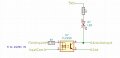
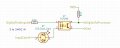
I came up with something I think will work but I'd like some opinions on it. The "Inputcom" can connected to gnd and 3-24v can be applied to the "Digitalfieldinput" (Sourcing) Or the "inputcom" can be connected to 3-24vdc and gnd can be applied to the "Digitalfieldinput" (Sinking)
I am just trying to locate a bidirectional LED preferably in a 603 package that will work in this circuit.
 

Attachments

Ya’akov

Joined Jan 27, 2019
9,072
If you do that, you need to put the current limiting resistor for the LED in series with it. There should be separate resistors for the optoisolator and the indicator.
 

Ya’akov

Joined Jan 27, 2019
9,072
Putting it in parallel with the optoisolator is fine, but that's when it needs it's own current limiting resistor. if scale the resistor for 3V and put a zener in there to limit the voltage, it will work at low and high voltages.
 

Thread Starter

jonfarrugia

Joined Feb 19, 2010
71
I don't need a polarity indicator but I didn't think the opto would handle the current required to drive the led. How would the new circuit look?
 

Thread Starter

jonfarrugia

Joined Feb 19, 2010
71
Perhaps your confused by the labels I was using. I've modified the drawing to show what I think you guys are suggesting.
Is this correct?
No this is not a school project, personal use.
 

Attachments

dendad

Joined Feb 20, 2016
4,452
That looks ok. But use pinMode(INPUT_PULLUP) to ensure the input does rise enough. Or add a pullup as well.
Have you calculated the input resistor to suit the opto transfer function so it switches well enough at both voltage extremes?
Also, the dissipation on full volts?
 

dendad

Joined Feb 20, 2016
4,452
You may get away with an 820R 1W resistor for the Opto input, and a 1K5 input LED resistor. Use a high intensity LED so less current is needed.
At 3V in, the Opto input current will be about 2mA, and that hopefully is enough to operate the Arduino input.
And at 24V input, the current is around 30mA. The 820R resistor will dissipate almost 700mW so make sure at least a 1W resistor is used.
Breadboard it to see.

The trick is to get enough input current to operate the opto at the low volts input, but not have excessive current or dissipation at the hi end.

Opto LED volts = 1.4.

3V in.
2mA input current.
R = (3-1.4)/.002
R = 1.6/.002
R = 800 (use 820R)

24V in.
I = (24-1.4)/820 = 27mA.

P = E x I
P = 24 x .027 <<< I ignored the opto LED voltage drop here
P = 0.648 Watts.
 
Last edited:
Top