why the dissipated power of my resistor are not equal?

Thread Starter

imijoon

Joined Jul 1, 2013
18
Hi my all friends,

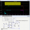
In the circuit bellow I have two similar resistor (Wirewound resistors) one for charging and other in discharge path. when the switch U1 is ON (at the time of 0.5s) the capacitor starts charging through R1. In this time a huge instantaneous power is dissipated in R1 and after about 1sec when the capacitor is fully charged the dissipation power exponentially goes to zero.
Now my capacitor is charged to 380VDC.
At the time of 4sec U1 turns OFF and U3 switches ON. At this time the capacitor discharges to R2. I expect that two resistor (R1 and R2) dissipate the same power but why R1 can withstand and R2 fails?


DGElder

Joined Apr 3, 2016
351
The power rating for a resistor is based on the max temperature before failure. Instantaneous power can't heat a resistor since the amount of energy delivered to the resistor approaches zero as the delta t approaches zero. It is the amount of energy delivered to the resistor over some span of time minus the amount of energy(heat) it can dissipate in that time that causes heating. The power rating on a resistor is the average power it can dissipate without failure.

Power through the resistors is proportional to the square of the voltage they see. And the rms voltage is what matters in the average power dissipation, not an instaneous voltage.. The rms voltage of the supply is 380/sqrt(2), the rms voltage of C1 after charging is initially nearly 380V. So initial power dissipation in R2 is greater than R1 by about a factor of 4.
 
Last edited:

Thread Starter

imijoon

Joined Jul 1, 2013
18
Thanks dear DEGlder,

But the voltage that my resistors see are not completely ac or DC. R1 see an ac voltage that exponentially is damped and R2 see a DC voltage that exponentially is damped. How can I measure the exact dissipated power of two resistors? I want an exact amount of dissipated power to compare mathematically.
 

DGElder

Joined Apr 3, 2016
351
Power is the rate of energy delivery or dissipation. The power dissipation in the resistors changes as the capacitor voltage changes, so it is a function of time. You would construct the function describing power vs time and then integrate it over some period of time to get the total energy dissipated; and then divide by that time to get the average power.
 

DGElder

Joined Apr 3, 2016
351
The energy dissipated by R2 is easy since it is just the total energy in the capacitor = 0.5*C*V^2. Divide by one second and you have average power dissipation over one second, or you could calculate over 5 RC time constants for example which would give a higher average power dissipation over a shorter time. It all depends on what you want to know and why you need that info. Also how frequently will this charge discharge cycle be executed as this will impact the heating of the resistor.

Are you trying to derive a formal equation for power dissipation in the two resistors or just trying to come to a practical solution for a safe power rating for the resistors? If the former you need to know calculus (at least for R1), if the later an approximation will do.
.
 
Last edited:

Thread Starter

imijoon

Joined Jul 1, 2013
18
The energy dissipated by R2 is easy since it is just the total energy in the capacitor = 0.5*C*V^2. Divide by one second and you have average power dissipation over one second, or you could calculate over 5 RC time constants for example which would give a higher average power dissipation over a shorter time. It all depends on what you want to know and why you need that info. Also how frequently will this charge discharge cycle be executed as this will impact the heating of the resistor.

Are you trying to derive a formal equation for power dissipation in the two resistors or just trying to come to a practical solution for a safe power rating for the resistors? If the former you need to know calculus (at least for R1), if the later an approximation will do.
.
I want to prove that the stress in R1 is less then R2. I want an equation to prove it.
 

crutschow

Joined Mar 14, 2008
34,472
Below is my LTspice simulation of the circuit.
It shows an energy dissipation of 101.6J for R1 and 132.5J for R2.
An explanation for the difference is left to the reader.
Hint: It's not the dissipation in the diodes, which is a little over 1J total for the 4 diodes.

upload_2016-6-29_12-31-59.pngupload_2016-6-29_12-33-44.png
 

Attachments

Last edited:

Thread Starter

imijoon

Joined Jul 1, 2013
18
Below is my LTspice simulation of the circuit.
It shows an energy dissipation of 101.6J for R1 and 132.5J for R2.
An explanation for the difference is left to the reader.
Hint: It's not the dissipation in the diodes, which is a little over 1J total for the 4 diodes.

View attachment 108472View attachment 108473
big thanks,

if there is only 31.5J difference between two resistor why R1 can withstand and R2 fails? my resistor is SWA06 Firstohm.
 

crutschow

Joined Mar 14, 2008
34,472
big thanks,

if there is only 31.5J difference between two resistor why R1 can withstand and R2 fails? my resistor is SWA06 Firstohm.
Well, 31.5J (31.5 watt-seconds) is a difference of about 30%, which is significant if you are operating near the resistor limits.
 
Last edited:

DGElder

Joined Apr 3, 2016
351
"if there is only 31.5J difference between two resistor why R1 can withstand and R2 fails? my resistor is SWA06 Firstohm."

What do you mean it fails? By what criteria?
What is the power rating? Is this pulse a one off or does it repeat every 5 seconds?
 

Thread Starter

imijoon

Joined Jul 1, 2013
18
"if there is only 31.5J difference between two resistor why R1 can withstand and R2 fails? my resistor is SWA06 Firstohm."

What do you mean it fails? By what criteria?
What is the power rating? Is this pulse a one off or does it repeat every 5 seconds?
Fail means that my resistor burns (damaged) and as it’s wirewound it opens. It's a 6W wirewound resistor. The pulse is repeated every 20sec. here is datasheet.
 

DGElder

Joined Apr 3, 2016
351
R2 is averaging 27W over 5 seconds which would be 6.7W average with 20 seconds between pulses. So a 6W resistor isn't good enough. You need about a 10W for R2 and the 6W resistor for R1 is marginal so I would go larger for that one as well.
 
Last edited:

crutschow

Joined Mar 14, 2008
34,472
That average is only 6.7W over the 20s interval but the peak power into R2 is nearly 3kW with an energy of 132.5 Joules so the resistor likely doesn't have the thermal capacity to handle such high surge energy and is burning out from that.
You probably should go to a 10W or larger resistor as DGElder suggested.
 

DGElder

Joined Apr 3, 2016
351
I agree with crutschow, 10W is the minimum I would try. Without an applicable power de-rating curve from the manufacturer you will have to estimate based on experiment. Start with 10W and measure the peak instantaneous temperature of the resistor under worst case conditions. You want to be well below the max temperature rating. Because of the pulsed nature of your circuit the internal temperature of the resistor will be higher than what you measure on the surface - more so than would be the case with a steady DC current. So be conservative. How conservative depends on many factors you have not shared, so it's up to you.
 
Last edited:
Top