 Facebook
 Google
 GitHub
 Linkedin
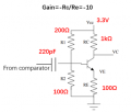
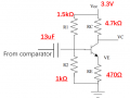
I would like to build an inverting amplifier with a gain of -10 as shown in the diagram. The BJT used is PN222A.

The input signal is one side of an LVDS wave, I used a capacitor(the 220pF) to level down the baseline to ground and the signal amplitude is negative.
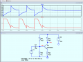
Here is the result I get, the green line is the input signal(after the capacitor), the blue line is the output. Apparently the BJT is not working.

Based on the calculation, VB=R2/(R1+R2)*Vcc=1.32V, in the middle of 0.7V and Vcc.
VE=VB-0.7V=0.62V
IE=(VE-0)/RE=1.3mA
Gain=-RC/RE=-10
Why doesn't this circuit work? Which value should I check?
Thank you.
Siyao
The input signal is one side of an LVDS wave, I used a capacitor(the 220pF) to level down the baseline to ground and the signal amplitude is negative.
Here is the result I get, the green line is the input signal(after the capacitor), the blue line is the output. Apparently the BJT is not working.
Based on the calculation, VB=R2/(R1+R2)*Vcc=1.32V, in the middle of 0.7V and Vcc.
VE=VB-0.7V=0.62V
IE=(VE-0)/RE=1.3mA
Gain=-RC/RE=-10
Why doesn't this circuit work? Which value should I check?
Thank you.
Siyao
Attachments
-
 18.1 KB Views: 11
 -
 30.8 KB Views: 11


")


