A sinewave oscillator generally has some frequency resonant circuit, since harmonic resonance naturally generates a sinewave, or a filter circuit that suppress the sinewave harmonics.
The phase-shift oscillator falls in the later category.
A phase-shift oscillator has several (3 minimum) RC low-pass filters in the feedback loop which cause a phase-shift that generates the oscillation. These also roll-off the high frequency components of the waveform, leaving a sinewave of the fundamental.
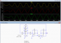
Below is the LTspice simulate of a three op amp phase-shift oscillator to illustrate this.
Each op amp has a phase-shift RC low-pass circuit in the local feedback loop. The circuit oscillates at the point where the phase shift in each RC circuit is 120°, giving the total feedback loop phase-shift of 360° required for oscillation.
As you can see, the first op amp (U3) output V(1) is somewhat distorted due to the diode limiters in the feedback loop (these prevent the op amp from saturating at the supply rails). The phase-shift components R4-C1 provide a low-pass rolloff of this clipping, otherwise the output at U3 would look like a square-wave.
The second op amp (U2) output V(2) has less distortion due to the filtering action of phase-shift components R2-C3.
The third op amp (U1) output V(out) is a fairly clean sinewave due to the further filtering action of phase-shift components R1-C2.
(The phase shift components are in the op amp local feedback path instead of the more conventional RC to ground configuration, but that makes no difference in the circuit operation.)

 Facebook
 Google
 GitHub
 Linkedin