Why is my LM317 current limiter circuit not working?

Thread Starter

bokeb

Joined Jul 9, 2021
4
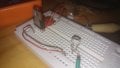
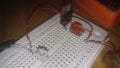
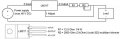
Noob here, but attempting to build a current limiter with a LM317 for use with a power supply to give constant current.

I have placed an extra potentiometer (the white one) to simulate changing load conditions - but when I adjust it, I am getting changing amperage - which if the LM317 was working correctly, I'm pretty sure it should not.

What am I doing wrong?
 

Attachments

Papabravo

Joined Feb 24, 2006
21,159
The LM317 is not a current limiter, and it cannot be used to force an arbitrary adjustable current into an adjustable load.
 

Thread Starter

bokeb

Joined Jul 9, 2021
4
See section 9.3.3 "Precision current limiter".
https://www.ti.com/lit/ds/symlink/lm317.pdf?ts=1625731381618&ref_url=https%3A%2F%2Fwww.ti.com%2Fproduct%2FLM317

What value did you calculate for your output current at minimum and maximum settings of your pot?
What value is your load pot?
What voltage are you getting across your load pot? Don't forget that the maximum output voltage of the LM317 is 3V less than your supply voltage.
The ammeter read 18.8 milliamps when the load pot was maxed, and 8 milliamps when the load pot was minimized
The load pot is reading 949 Ohms max, 2.4 Ohms min
I'm reading 7.58 Volts across the load pot when maximized

Aha - I am reading 8.5 volts across the LED I am using (I guess it's not exactly meant for this small stuff)
The power supply is a 19.5v laptop charger, so 7.58v load pot + 8.5v LED + 3v LM317 = 19.08v total... probably cutting it too close?
Idk, am I doing that right? I really am a noob.
I will try replacing the LED with a 10 Ohm resistor.
 

Deleted member 115935

Joined Dec 31, 1969
0
The ammeter read 18.8 milliamps when the load pot was maxed, and 8 milliamps when the load pot was minimized
The load pot is reading 949 Ohms max, 2.4 Ohms min
I'm reading 7.58 Volts across the load pot when maximized

Aha - I am reading 8.5 volts across the LED I am using (I guess it's not exactly meant for this small stuff)
The power supply is a 19.5v laptop charger, so 7.58v load pot + 8.5v LED + 3v LM317 = 19.08v total... probably cutting it too close?
Idk, am I doing that right? I really am a noob.
I will try replacing the LED with a 10 Ohm resistor.
The circuit works by keeping the voltage across R1 + R2 constant, at Vref for the LDO, which I think is 1.5v , or it could be 1.2 , please check data sheet

So measure voltage across R1 + R2 ,

The max current the circuit can provide with your values is around 120 mA,
what current does you load need ?

The circuit can also only work within the voltage range on the input,

As you have put the pot within the feedback loop of the LM317
as you adjust the resistance, the current the 317 puts through the R1 + R2 pair will vary , to keep the voltage drop across the pair a constant

You can easily check this with a voltage meter across R1 + R2, and vary the pot, you should see the current vary ,

i.e. what you are doing with R2 is not simulating changing load resistance.

but at 120 mA,
I have not checked, but I'd suggest that the pot is going to have fun time taking the current.
 

Papabravo

Joined Feb 24, 2006
21,159
Sorry, disagree, the 317 makes a great constant current circuit
The original post was a bit confusing on that score referring to both current limiting and constant current, but his observation was that the constant current source was not behaving in that fashion. There is a bit of a disconnect here. It is true for example that you cannot force 100 mA of current into a 1kΩ load no matter what you try. That was my point.
 

Thread Starter

bokeb

Joined Jul 9, 2021
4
Hello,

There is also a thread running from the same user at Electronics Point:
Why is my LM317 current limiter circuit not working?

We can see what is already give over there.

Bertus
yes sorry for the parallel posts, wasn't sure where the best place to ask was. Will continue on the Electronics Point thread.

The original post was a bit confusing on that score referring to both current limiting and constant current, but his observation was that the constant current source was not behaving in that fashion. There is a bit of a disconnect here. It is true for example that you cannot force 100 mA of current into a 1kΩ load no matter what you try. That was my point.
I have the feeling that this probably evokes the essence of my problem, but I do not yet have enough comprehension in this area to understand this logic. Sorry and thank you haha
 

Thread Starter

bokeb

Joined Jul 9, 2021
4
The circuit works by keeping the voltage across R1 + R2 constant, at Vref for the LDO, which I think is 1.5v , or it could be 1.2 , please check data sheet
it's 1.25v
So measure voltage across R1 + R2 ,

The max current the circuit can provide with your values is around 120 mA,
what current does you load need ?
The end product will ideally have R2 (as a pot) be able to vary I Out from 5 mA to 30 mA
The circuit can also only work within the voltage range on the input,

As you have put the pot within the feedback loop of the LM317
as you adjust the resistance, the current the 317 puts through the R1 + R2 pair will vary , to keep the voltage drop across the pair a constant

You can easily check this with a voltage meter across R1 + R2, and vary the pot, you should see the current vary ,

i.e. what you are doing with R2 is not simulating changing load resistance.
Sorry I guess I was not very clear - the diagram I posted is the ideal end design I am aiming to build, however I placed an extra potentiometer to simulate changing load conditions - outside the the LM317 loop - I tried to get a couple good shots of how I built it on the board. It is that pot that I was adjusting to test if the current changed, and even so, it did. the R2 pot I did not adjust, it was functioning as a normal resistor.
but at 120 mA,
I have not checked, but I'd suggest that the pot is going to have fun time taking the current.
Not quite certain I understand this in the correct context. Sorry (all) for the confusion regarding adding an extra pot not indicated in the diagram.
 

Deleted member 115935

Joined Dec 31, 1969
0
please place a corrected circuit
what is the point of r2 then ?

how much current does the load take at what voltage

for tests , better to us a resistive load
 
Top