Why is copper the most widely used to make coils?

Ya’akov

Joined Jan 27, 2019
10,278
The problem is that the variable capacitors i have only have discrete values:
View attachment 171536
You need the cap to be on the loop as a trimmer, not for the larger design but for the very narrow tuning function. It could be quite a small value if you get high tolerance parts and design well. You can also rig up a mechanical way to shorten and lengthen the loop as the circuit sees it.
 

Thread Starter

Mariemation

Joined Sep 26, 2016
18
Maybe i can add a resistor to the circuit to lower Q factor, but i am not sure how that is going to affect the efficiency of the WPT.
 

Thread Starter

Mariemation

Joined Sep 26, 2016
18
You need the cap to be on the loop as a trimmer, not for the larger design but for the very narrow tuning function.
Can you please explain to me what you mean by 'the cap' and 'tuning function' (i am sorry, it's just that i study physics in french so i am not used to english terms yet)
 

Ya’akov

Joined Jan 27, 2019
10,278
Can you please explain to me what you mean by 'the cap' and 'tuning function' (i am sorry, it's just that i study physics in french so i am not used to english terms yet)
Cap is short for capacitor. To make your loop resonant, the inductance and capacitance must be precisely selected for the actual conditions of the components once it is assembled. Choosing the components carefully, and ensuring they are very close to the theoretically specified values is important, but once they are assembled, the various deviations from ideal will add up and the circuit will not be the same as the math you did in theory.

“Trimmer” components (in this case a capacitor) are intended to compensate for the practical deviations from the theoretical. The trimmer capacitor, in this case, could simply be a value to add or subtract from the fixed capacitor to tune the loop into resonance. That’s the tuning function.

You will have to make some empirical changes to the inductance and/or capacitance values in the built loop to make it resonant, that’s how things actually work.
 
Last edited:

MisterBill2

Joined Jan 23, 2018
28,031
The problem is that the variable capacitors i have only have discrete values:
View attachment 171536
If all that is available is fixed capacitors then there is a trick that is available if yiu have some insulated wire. It is known as a "gimmick" capacitor, and it is formed by twisting two wires tightly together. At least one of the wires must have insulation, so as to avoid creating a short circuit. The capacitor that it forms is a small value, typically between 1 and 10 picofarads per inch, depending on insulation thickness, tightness of twist, and wire size. But usually such a capacitor can serve the purpose of providing additional capacitance. And usually they are fairly high Q and low loss. So that is one option for adding capacitance if the fixed capacitors are not quite enough, if you have some wire available. If all that you have is test leads with connectors on the ends then that presents another challenge.
Is this a classroom project? Or a homework assignment? Are the coils that you have non-adjustable?
"Tuning Function" is the same as "adjusting to resonance at a specific frequency".
 

Thread Starter

Mariemation

Joined Sep 26, 2016
18
If all that is available is fixed capacitors then there is a trick that is available if yiu have some insulated wire. It is known as a "gimmick" capacitor, and it is formed by twisting two wires tightly together. At least one of the wires must have insulation, so as to avoid creating a short circuit. The capacitor that it forms is a small value, typically between 1 and 10 picofarads per inch, depending on insulation thickness, tightness of twist, and wire size. But usually such a capacitor can serve the purpose of providing additional capacitance. And usually they are fairly high Q and low loss. So that is one option for adding capacitance if the fixed capacitors are not quite enough, if you have some wire available. If all that you have is test leads with connectors on the ends then that presents another challenge.
Is this a classroom project? Or a homework assignment? Are the coils that you have non-adjustable?
"Tuning Function" is the same as "adjusting to resonance at a specific frequency".
Yes it is a school project
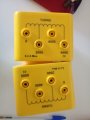
The coils i have are actually taken off of a transformer i can only control the number of turns i am using, and they are inside a plastic box:coil.jpg

I don't have the exact value of their inductance so i calculated it experimentally for 6000 turns, and that's where i've found 0.15 H

but i do have enamel wire available, so i can make a gimmick capacitor.
 
Top