Why do only two of four MOSFETS get hot ?

Thread Starter

hugoVS

Joined Jun 6, 2019
3
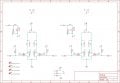
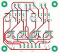
So I have made a H-bridge with two relay and four IRF520N mosfets. I control them with my microcontroller secured with an ULN2803. However when I connect +5V to the H-bridge board and +12V for the motors only mosfet T21 gets really hot and T22 als gets a bit warm. What could cause it ?

hbrug bord.JPG h-brug boek.JPG
 

Attachments

AlbertHall

Joined Jun 4, 2014
12,347
IRF520N needs 10V between the gate and source to turn on fully and be really low resistance. You are applying only 5V which means the FET will be higher resistance and hence dissipating lots of power.
 

crutschow

Joined Mar 14, 2008
34,469
What could cause it ?
Not reading the data sheet. :rolleyes:

The MOSFET's Vgs threshold voltage can vary significantly from unit to unit (see below), so ones with a higher threshold, will have a higher on-resistance with only a 5V Vgs, and thus dissipate more power for a given drain current.

upload_2019-6-6_11-57-22.png

Note the Vgs voltage of 10V for testing the on-resistance of the IRF520N (below).
You need a logic-level type MOSFET where the on-resistance is rated at a Vgs of 5V or less.

upload_2019-6-6_12-2-17.png
 

Alec_t

Joined Sep 17, 2013
14,335
Depending on your FET drive signals and the pick-up/drop-out times of the relays it seems to me that the relay switches K1 and K2 each provide a possible path for short-circuiting the 12V supply?
 

mlsirkis

Joined Aug 11, 2010
32
Depending on your FET drive signals and the pick-up/drop-out times of the relays it seems to me that the relay switches K1 and K2 each provide a possible path for short-circuiting the 12V supply?
Read data sheet
Understand data sheet
Follow data sheet
 

Thread Starter

hugoVS

Joined Jun 6, 2019
3
Depending on your FET drive signals and the pick-up/drop-out times of the relays it seems to me that the relay switches K1 and K2 each provide a possible path for short-circuiting the 12V supply?
I only put a signal on the first relay and two mosfets with a delay to prevent shortcircuit . However these two didn't get hot.
 

Thread Starter

hugoVS

Joined Jun 6, 2019
3
Not reading the data sheet. :rolleyes:

The MOSFET's Vgs threshold voltage can vary significantly from unit to unit (see below), so ones with a higher threshold, will have a higher on-resistance with only a 5V Vgs, and thus dissipate more power for a given drain current.

View attachment 179187

Note the Vgs voltage of 10V for testing the on-resistance of the IRF520N (below).
You need a logic-level type MOSFET where the on-resistance is rated at a Vgs of 5V or less.

View attachment 179188
Vgs wasn't the problem why only two Mosfets got hot. I only controlled the first two Mosfets causing a floating signal on the other two, that's probably why they got hot. Now I control four of them and not a single one gets hot.
 

crutschow

Joined Mar 14, 2008
34,469
Vgs wasn't the problem why only two Mosfets got hot. I only controlled the first two Mosfets causing a floating signal on the other two, that's probably why they got hot. Now I control four of them and not a single one gets hot.
Okay, you lucked out with some MOSFETs that have a lower than maximum Vgs threshold voltage.
But for future good design practice, always use logic-level type MOSFETs if the Vgs control voltage is <10V.
 
Top