Why do I keep burning mosfets

Thread Starter

Simranjit

Joined Apr 16, 2024
41
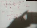
Hi, I am working on Tesla coil. So I far I have destroyed over 15 MOSFETs (irf540n). I cant seem to figure out why. I tried adding hyperfast rectifier diode (30eth06) in parallel with mosfet. I have tried using different power supplies for logic and mosfet. I'm really frustrated with this and I can't seem to pinpoint the issue. The oscilloscope shows Tesla coil oscillating at 90kHz (1900 turns secondary, 3 turns primary). The antenna also works hit or miss. Sometimes I have to touch the antenna to make circuit work (I'm guessing charge gets accumulated on antenna). Please help me with the mosfet issue (that is my main issue).
 

Attachments

Last edited:

Wendy

Joined Mar 24, 2008
23,798
Again how much current are you trying to use? Help me help you. Measure the current. Next step I'll try redrawing your schematic to see if we are on the same page.
 

Thread Starter

Simranjit

Joined Apr 16, 2024
41
Again how much current are you trying to use? Help me help you.
I'm sorry if I'm not understanding you question. For testing phase I have current limited the power supply to 1.5A @ 12v. I would assume that mosfet IRF540n would survive because it is listed for 100v and 23-33A. The current never usually goes above 900ma but the mosfet burns out the power supply automatically switches to over current protection mode. I checked the mosfet leads with multimeter and the are all shorted.
 
Last edited:

crutschow

Joined Mar 14, 2008
38,389
You are likely exceeding the safe operating area of the MOSFET (below).
You will need an oscilloscope to see if that's what's happening.

Note that the peak current is likely much higher than the 900mA average current from the power supply.
Try putting a small series resistor in series with the primary to limit the peak current to a few amps.

1715399064258.png
 

Thread Starter

Simranjit

Joined Apr 16, 2024
41
You are likely exceeding the safe operating area of the MOSFET (below).
You will need an oscilloscope to see if that's what's happening.

Note that the peak current is likely much higher than the 900mA average current from the power supply.
Try putting a small series resistor in series with the primary to limit the peak current to a few amps.

View attachment 322058
Hi, new mosfets are coming tomorrow. I will update you once they show up. I will try to learn more about safe operating area of mosfet and how to check it with oscilloscope. Thank you.
 

MisterBill2

Joined Jan 23, 2018
27,271
There are three electrical causes of active device failure, excess voltage breakdown, excess current burnout, or excess power overheating. Operating outside the given safe operating area will lead to at least one of these causes.
Have you monitored the temperature of these while operating? In addition, there may be too slow of a switch on time, so that there is excessive heating during the switching on interval. The switch-on drive may not be adequate. The gate drive signal may be the problem.

Of course, given that we only are shown a small part of the circuit, it might be from something we do not see.
How long to the MOSFETS last before they fail??? Seconds or minutes, or almost instantly??
 
Last edited:

Wendy

Joined Mar 24, 2008
23,798
Feeling components with my index finger was a tried and true technique to see if a component was stressed or not. That is until you burn your finger and create a reverse image brand of the transistor on said finger. This happened to me several times.
 

Wendy

Joined Mar 24, 2008
23,798
Here is the promised drawing I did make some changes and some corrections just let me know if it helps.
MOSFET.png
you really do not need base resistors for the transistor drivers, but it does protect against certain failure modes. The diode shown on Q3 is part of the transistor.
 
Last edited:

ThePanMan

Joined Mar 13, 2020
864
Here is the promised drawing I did make some changes and some corrections just let me know if it helps.
you really do not need base resistors for the transistor drivers, but it does protect against certain failure modes. The diode shown on Q3 is part of the transistor.
I'm the last one to ask this question, but are Q1 & Q2 backwards? Q2 should be on top? No?
 
Top