Why can't I simulate this exponential converter?

Thread Starter

devinw

Joined Dec 2, 2018
32
Hi all! I'm trying to simulate a very simple and well-known circuit in synthesizers which takes a 1 Volt/Octave input and outputs an exponential current (which usually goes to something like an OTA). However, I can't seem to get this to work at all. I've tried it with the little toy simulator on Falted and also with LTSpice. No dice. What am I missing here?

I'm running a simplified version of the expo converter part of this:
https://www.birthofasynth.com/Thomas_Henry/pdf/VCO-1/vco1_schem1.pdf

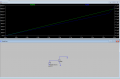
And I get this (not what I'm expecting, which is an exponential current increase with increasing control voltage at the input):
 

Attachments

Thread Starter

devinw

Joined Dec 2, 2018
32
The cap doesn't even need to be there. It's just to block an DC component if you are using the frequency modulation input (which I've omitted). The exponential part still should work, no? I'm told this ciruit has been built by plenty of people and works fine. But, as my simulation shows, I'm screwing something up.
 

Jony130

Joined Feb 17, 2009
5,487
The exponential part still should work, no?
Well yes. But as I said early your BJTs are OFF. And you can expect the exponential part from a BJT only when the BJT is ON.
The collector current is an exponential function of a Vbe voltage (Shockley equation).
 

Thread Starter

devinw

Joined Dec 2, 2018
32
There should be a exponential current increase through the collector when Vbe increases, right?

I guess my question is, why are the BJTs turned off in this circuit, and how does it manage to work in real life (which it supposedly does)?

Pardon my ignorance, and really thanks for any help here. It is much appreciated!. I'm getting good with electronics these days, but transistors still seem to be a bit of black magic for me. :(
 

Thread Starter

devinw

Joined Dec 2, 2018
32
To make it even simpler, I just put a NPN BJT in and varied the Vbe from zero to 180mV and plotted the collector current. From everything I've read, in this region it should be exponential, but I get a line with a little kink. So, something is wrong methinks.
 

Attachments

Jony130

Joined Feb 17, 2009
5,487
and how does it manage to work in real life
Because you have skipped the very important component in this circuit the op-amp. Try to google the logarithmic amplifier.
http://www.ti.com/lit/an/snoa575b/snoa575b.pdf

Try this circuit

1.png


2.PNG
I just put a NPN BJT in and varied the Vbe from zero to 180mV and plotted the collector current
For the NPN BJT's the Vbe voltage needs to be larger than 500mV. But I doubt that you will be able see "exponential" versus time.
Because in BJT Ic current is an exponential of a Vbe voltage not the time.
https://forum.allaboutcircuits.com/blog/fun-with-the-diode-equation.589/#comment-1283
 

Attachments

Last edited:

Thread Starter

devinw

Joined Dec 2, 2018
32
Where is your Vout on that ciruit? It looks like you are putting a 50uA current source where the original circuit said it was providing an exponential current (which is what I want).?

Also, on the simple BJT simulation, I just put a ramp of Vbe from 0 to 180mV that happens over 1 second, but time doesn't really matter. That's just the only way I know how to plot Ic vs Vbe besides doing discrete steps in steady state and plotting them in Excel. But, there probably is an easier way, I'm just not a ninja in LTSpice :D.
 

Jony130

Joined Feb 17, 2009
5,487
Where is your Vout on that ciruit? It looks like you are putting a 50uA current source where the original circuit said it was providing an exponential current (which is what I want).?
At the output of U2 opamp where I marked 1V per octave.

That's just the only way I know how to plot Ic vs Vbe besides doing discrete steps in steady state and plotting them in Excel. But, there probably is an easier way, I'm just not a ninja in LTSpice
See the simulation file
 

Attachments

Thread Starter

devinw

Joined Dec 2, 2018
32
Interesting! So I just needed to put a positive voltage on the collector. Damn.

The odd thing is that the OTA (CA3080) shown on the original schematic, I'm pretty sure has the amplifier bias pin at 2 diode drops below the negative rail (so about -13.6V), so I don't even see how that works!
 

Jony130

Joined Feb 17, 2009
5,487
I'm pretty sure has the amplifier bias pin at 2 diode drops below the negative rail (so about -13.6V), so I don't even see how that works!
The datasheet says one diode drop above the negative rail. And pin 5 current of an OTA needs to enter this node (source current/ flow into this pin2).
And this current is provided by Q6 (PNP) transistor. And this current will leave the Q6 collector terminal and enter into the OTA pin 5.
In the original circuit the IC2b forms a logarithmic amplifier. And for the negative input voltage (for IC2b) we will have a positive voltage at the output (pin 7). And this positive voltage will turn on the Q5 and Q6.

https://electronics.stackexchange.c...r-npn-by-looking-at-the-circuit/424706#424706

See the simulation file
 

Attachments

Thread Starter

devinw

Joined Dec 2, 2018
32
AHA! So it was the op amp, whose feedback loop bascially includes the NPN transistor that I was missing! Works like a charm! I had thought this op amp was just to mix in the linear FM voltage! THANK YOU!
 

Thread Starter

devinw

Joined Dec 2, 2018
32
BTW, thank you for that link to the log amp article too! That was very very helpful in helping me see what's going on here!
 
Top